Reducing Multi-tap Electrical Fires using Microcapsule Fire Extinguishing Patches
Article information
Abstract
The fire at the Coupang Deokpyeong Logistics Center has spurred studies to reduce the damage caused by multi-tap electrical fires. One solution is a microcapsule fire extinguishing patch with a built-in fire extinguishing agent. To confirm the efficacy of the fire extinguishing patch in curtailing electrical fires, a complex electrical fire in a multi-tap due to overload and tracking was simulated. In the absence of the fire extinguishing patch, continuous flame discharge occurred as the overcurrent reacted with internal combustibles, resulting in a short circuit due to final tracking and a risk of exposure to flames at 1,187s. In contrast, when an overload was applied to the multi-tap with the fire extinguishing patch for 2,400 s, the fire extinguishing agent stored in the microcapsule was released, preventing ignition of the combustibles inside the multi-tap and the formation of the carbonic electric conductive pass due to cooling, suffocation, and anticatalyst effects. Therefore, the overload did not lead to a fire, confirming the ability of the patch to retard electrical fires in the multi-tap. Evaluation of the effect of the location of the fire extinguishing patch showed that the fire extinguishing effect was most significant when the fire extinguishing patch was attached inside the multi-tap.
1. Introduction
According to the National Fire Information System Fire Statistics [1] of the National Fire Agency, 36,267 fires occurred in 2021. Analysis by ignition factor showed that carelessness accounted for the highest proportion (16,873 fires; 46.5%), followed by electrical factors (9,474; 26.1%), mechanical factors (4,033; 11.1%), unknown factors (3,088; 8.5%), and chemical factors (683; 1.9%). Among the ignition factors, electrical factors appear to be the main cause of fires every year as a single cause, excluding carelessness. Given that electrical factors have continued to gain prominence as an ignition factor in the recent three years, increasing from 23.6% in 2019 to 24.1% in 2020 and 26.1% in 2021, various studies are necessary to reduce electrical fires, along with effective governmental countermeasures to prevent electrical fires.
In indoor wiring, an electrical outlet is an adapter for a power supply that is connected by inserting a power plug to obtain a current required for using an electric device. A multi-tap, which is typically used as an electrical outlet, acts the same as an outlet, but is a mobile multi-outlet that is movable and is connected to a fixed outlet such that several plugs can be plugged in and used at once. In the case of an outlet fixed to a wall, most multi-taps have 2-4 sockets, and thus, there is a limit to using the power of various electric devices at the same time. Moreover, for using various mobile devices such as fans, heaters, and refrigerators, there are problems with inconvenient connections such as distance and spatial constraints at wall-mounted outlets. To solve this problem, the multi-tap is the most commonly used electrical appliance, along with fixed outlets mounted on walls. Although these multi-taps require careful attention during use, most of them are used while overlooking the risk of fire, and hence, they are susceptible to the risk of an electrical fire. In other words, because the multi-tap can be used and installed in various locations, it is highly likely to be exposed to external environments, which may cause an electrical fire due to tracking in dust and humid environments and overload due to overloading of a power strip that ignores allowable current. As a result, the fire statistics [1] in 2021 also showed that outlets (20.8%) and switch multi-taps (11.0%) accounted for the highest (31.8%) of all 2109 fires in wiring/wiring appliances, and thus, it is time to design various measures to ensure fire safety for outlets and multi-taps.
The 2019 Cheonan Ramada Hotel Fire was a major fire that caused twenty casualties, including one death. The cause of the fire was electrical breakdown in a two-hole outlet located on the wall of a bedding storage room (linen room) illegally installed in the parking lot on the first basement floor, due to electrical factors [2]. In 2021, the fire at the Coupang Deokpyeong Logistics Center lasted for six days and caused two casualties, including the death of one firefighter, making it a social issue. The cause of the fire is presumed to be an electrical fire in the outlet, as smoke, sparks, and flames coming from the multi-tap were filmed by CCTV installed in the logistics warehouse [3]. Various studies are being carried out to prevent outlet fires in the wake of the Cheonan Ramada Hotel Fire and the Coupang Deokpyeong Logistics Center Fire. In the case of a fire in the existing switchboard and distribution board, a fixed automatic fire extinguishing device has been developed for local application in small spaces to prevent fire in a fixed space. However, a fixed fire extinguisher is inevitably required for multi-taps that are used in variable locations and are transferred among outlets. Thus far, an automatic fire extinguishing multi-tap coated with a fire extinguishing material has been developed, but to utilize this system, all of the existing multi-taps must be replaced, which is a practical limitation. Accordingly, a microcapsule fire extinguishing patch capable of suppressing fires after attachment to an existing outlet or multi-tap is coming to the fore. Although the main aim of prior studies on microcapsule fire extinguishing patches [4,5] is to reduce electrical fires, most of the studies did not check the performance of the developed system by causing an electrical fire, but instead, caused a fire using a flammable liquid in a dead electrical device and checked a simple fire extinguishing effect. In this study, in order to investigate the effect of the microcapsule fire extinguishing patch on reducing multi-tap electrical fires, complex electrical fires due to overload and tracking are simulated to analyze the efficacy of the patch for reducing electrical fires by comparing cases with and without the fire extinguishing patch. The effect of the patch location on the effectiveness for fire extinguishing is also confirmed.
2. Theoretical Background
Research on microcapsule extinguishing agents using Novec 1230 by 3M is being performed worldwide. Zhang et al. [6] studied fire extinguishing in a lithium-ion battery using a microcapsule fire extinguishing agent with a core@shell structure. Lee et al. [4,5] studied the fire extinguishing adaptability of microcapsules in small-space fires such as distribution boards. Furthermore, Lee et al. [7] developed a fire extinguishing wallpaper containing microcapsules and conducted a study on fire suppression.
In this study, G's microcapsule fire extinguishing patch is used. The core material is the fire extinguishing agent Novec 1230, a fluorinated ketone (CF3CF2C(O)CF(CF3)2) 'FK- 5-1-12' manufactured by 3M, for which the structural formula and a 3D molecular structure are shown in Figure 1. This material is non- conductive in both the liquid and gaseous states and is a halon substitute, containing no chlorine or bromine; thus, the possibility of destroying the ozone layer is zero. Moreover, the global warming potential (GWP) is less than 1, reducing greenhouse gas emissions by 99.9% compared to hydrofluorocarbons (HFCs) and making it one of the most environmentally sustainable fire extinguishing agents.
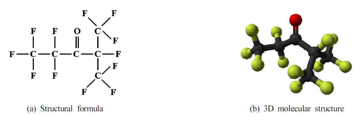
Structural formul a (a) and 3D molecular structure (b) of 'FK-5-1-12'.
By mixing the core material with a first colloidal solution, second colloidal solution, precipitating agent, and coagulant, the colloidal solution is precipitated and cured to form the core@shell structure at the interface, thereby forming a microcapsule (150 to 350 um) with a high-density non-porous multilayer structure as an outer wall. The microcapsule thus formed and the polymer are stirred and mixed to form a fire extinguishing patch that is easy to attach. Figure 2 presents scanning electron microscope (SEM) images of the microcapsule and the structure of the fire extinguishing patches. As the core material in the fire extinguishing patch changes phase from liquid to gas at a specific temperature of ~120-150 °C, the vaporizing force sprays a large amount of the material inside the capsule to extinguish the initial fire. In other words, the fluorinated ketone, which is the fire extinguishing agent inside the core, absorbs surrounding energy and cools down the surroundings due to its high vaporization power and strongly endothermic reaction, has a suffocating effect, and blocks chain reactions through an anticatalyst reaction, thereby extinguishing fires [8-10].

SEM image (a) and structure (b) of microcapsule fire extinguishing patch.
3. Experimental
3.1 Experimental sample
To analyze the efficacy of the microcapsule fire extinguishing patch (hereinafter referred to as the fire extinguishing patch) for reducing electrical fires, a commonly used multi-tap (4 outlets) was selected as a sample, as shown in Figure 3, and the experiments were carried out under the same conditions by grouping the multi-tap samples into 'no-attached patch' (NAP) and 'attached patch' (AP) depending on whether or not a fire extinguishing patch was attached.
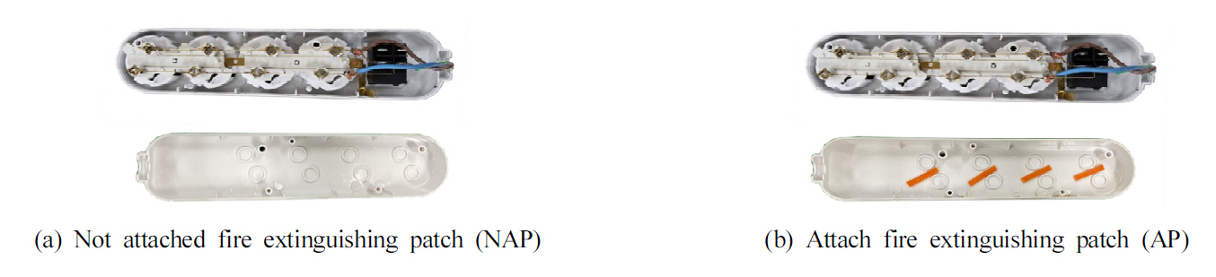
Experimental samples.
3.2 Experimental methods
To overload the power strip on the multi-tap and induce multi-tap firing by internal pollutants as in the case of the Coupang fire, the experiments were performed under conditions simulating a complex electrical fire due to overload and tracking. These conditions were chosen because electrical fires are not generated only by a single cause, but are generated and develop due to complex causes such as exposure to various degrading factors depending on the environment in which the multi-taps are employed, including the presence of dust and moisture [11-13]. Figure 4 shows a schematic diagram of the experiment used to confirm the effect of the fire extinguishing patch on curtailing a multi-tap electrical fire. To examine the effectiveness of the fire extinguishing patch for reducing electrical risk in the multi-tap by simulating only the multi-tap fire, the extreme condition of 64 A overload was applied to the multi-tap for 1800 s using a load tester, and the overload blocking device, which is a safety device attached to the multi-tap itself, was prevented from operating. Moreover, because the multi- tap itself is a flame retardant, in the absence of internal contamination, the plastic case melts and collapses rather than firing occurring in the multi-tap itself. Therefore, internal contamination was simulated. The experiment was conducted by adding two sheets of tissue, 2.5 g of sawdust, and 2.5 g of sodium nitrate inside the multi-tap to simulate the accumulation of dust and foreign substances due to environmental pollution. All experiments were conducted more than five times and data representing high fire risk were used. The thermal properties of the samples with and without an attached fire extinguishing patch were analyzed by using thermal imaging cameras (Testo 890, Testo Co., Germany) and camcorders. Electrical overload wad applied internally. Therefore, a thermocouple had to be installed in the test device, and thus, there was a limit to measuring the exact internal temperature. For this reason, only the external temperature was measured.
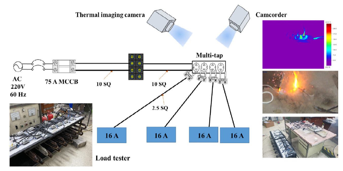
Schematic diagram of experimental setup.
To investigate the efficacy of fire extinguishing when the patch was attached at different positions, the experiment was performed by attaching the fire extinguishing patch to the inside of the multi-tap, the bottom of the socket, and the side of the socket, as shown in Figure 5. The internal combustibles were employed under the same conditions as in the experiment for confirming the effect of the fire extinguishing patch in curtailing the multi-tap electrical fire. To identify the fire extinguishing effect for each attachment position, tissue was attached between both ends of the plug, and 1 ml of 3% saltwater was injected to form a primary tracking conductive path in order to materialize a flame exposure situation due to forced tracking at the point where the plug and socket were connected. Afterward, the experiment was performed by continuously adding 1 ml of saltwater to the surface of the plug every 2 min. Here, two plugs were connected and a current of 16 A per plug and a total of 32 A was applied. The experiment was terminated if flames were continuously generated due to tracking, power was cut off due to disconnection of the circuit breaker or the track accompanied by flame discharge, or no tracking progress appeared. The experiment was conducted three times for each sample and analysis was carried out for data with the highest risk.
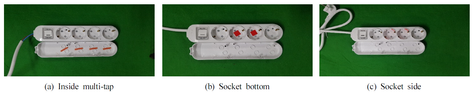
Locations of fire extinguishing patch.
4. Results and Discussion
4.1 Effect of attachment of fire extinguishing patch on electrical fire in multi-tap
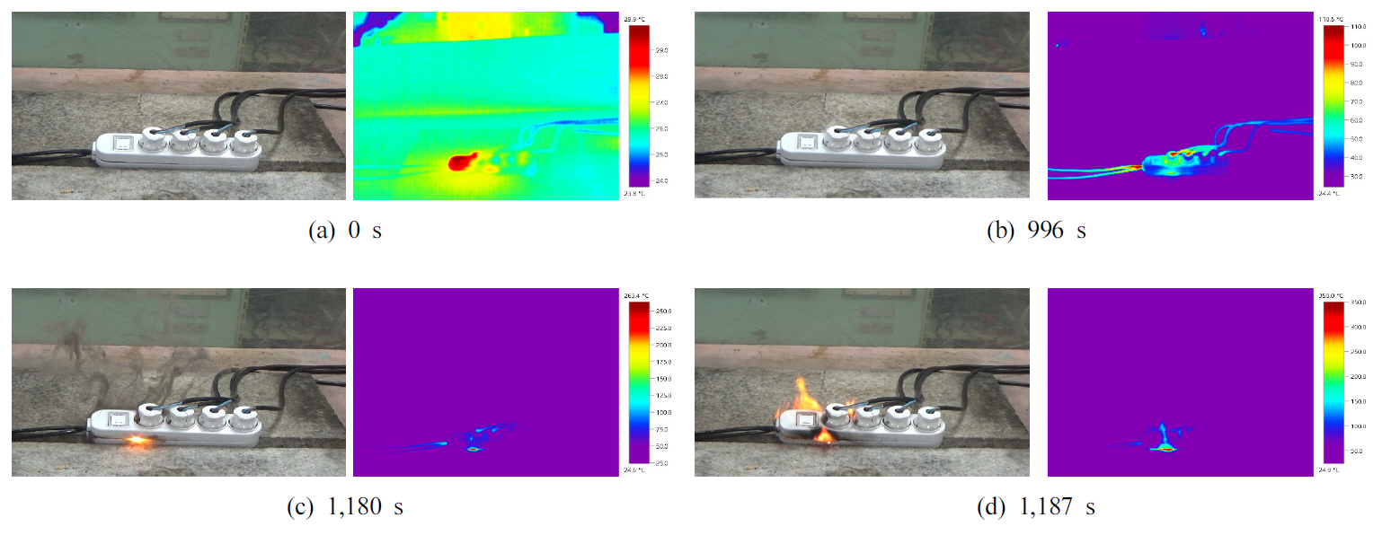
Figure 6 shows the experimental results for the samples without fire extinguishing patches. The internal combustibles in contact with the metal knife rest were pyrolyzed at 996 s due to the temperature increase attributed to overload, resulting in the first white smoke. As the temperature of the metal knife rests rapidly increased at 1,180 s, the multi-tap was exposed to extreme heat, and the internal combustibles and plastics inside the case were incompletely combusted, accompanied by thick black smoke. It is also believed that flame discharge due to leakage current occurred as the internal material between the metal knife rests was carbonized to form a conductive path. Thereafter, continuous flame discharge was initiated at 1,187 s. About 7 s later, the internal carbonization and degradation increased, and the conductive track grew and a short circuit caused by tracking occurred, resulting in firing with explosion. The maximum temperature at the moment of firing was measured to be 350.0 ℃ because the measurement range of the thermal imaging cameras (0-350 °C in section 1 or 350-1200 °C in section 2) was set to a maximum of 350 °C to accurately analyze the initial temperature rise, whereas the actual temperature is judged to have risen higher. Furthermore, in the case of the samples without fire extinguishing patches, fires generally occurred before 1,800 s, which is the overload application time.
Effect of internal combustibles on NAP.
Figure 7 presents the experimental results for the sample with the fire extinguishing patch. Fine white smoke was observed with the sound of the fire extinguishing patches popping at 600 s due to the temperature increase attributed to overload. The fine white smoke is considered to be generated by pyrolysis of gas or internal combustibles released by popping the microcapsules of the fire extinguishing patches as it is not possible to check the internal situation. Here, the temperature measured from the outside was 89.3 °C. In the case of the samples with fire extinguishing patches, the thick black smoke or ignition phenomenon that was observed in the samples without fire extinguishing patches was not observed, and the temperature was maintained at 109.0 °C even after 1,800 s, which is the overload application time. Therefore, the thermal properties were further observed up to 2,400 s. Although the temperature increased to a maximum of 115.8 °C at 2,400 s, which is the end time of the experiment, external risk characteristics were not identified under this experimental condition, except for the generation of a small amount of white smoke.

Effect of internal combustibles on AP.
Figure 8 shows the internal burnout characteristics after the experiment, where it was confirmed that the sample without the fire extinguishing patch had relatively more severe burnout damage compared with the sample with the fire extinguishing patch. In other words, in the case of the sample without a fire extinguishing patch, the degree of fire damage, such as carbonization and melting of the internal combustibles and plastic case, was quite severe, starting from the part of the socket around the power line to which power is supplied. However, in the case of the sample with the fire extinguishing patch, only some carbonization was observed in the part of the socket around the power line, and the plastic case was not damaged. Moreover, the combustibles around the fire extinguishing patch were wet with some soot and steam, which was generated by vaporization of the fire extinguishing patch. The microcapsules burst around the fire extinguishing patch, showing signs of droplet-shaped scattering. Accordingly, it is considered that the fire extinguishing patch reacts to heat generated under overload and prevents the firing of combustibles inside the multi-tap by the cooling, choking, and anticatalytic effect of the fire extinguishing agent released as the internal microcapsule explodes. It is also thought that the non-conductive fire extinguishing agent prevents the formation of a carbonization conductive path through the conductive material, thereby preventing shortcircuiting at both ends of the metal knife rest and preventing a fire. In all samples, the burnout of the 1st socket close to the power line was severe, whereas the burnout of the 4th socket far from the power line was weak. This is because due to the current flow direction, a current of 64 A flows in the 1st part of the socket close to the power line, a current of 48 A flows in the 2nd part of the socket, a current of 32 A flows in the 3rd part of the socket, and a current of 16 A flows in the 4th part of the socket; thus, the temperature increased rapidly in the 1st part of the socket, which receives relatively large overcurrent based on Joule's law: H = 0.24 I2RT [cal].

Damage characteristics in multi-tap.
4.2 Effects of patch position on fire extinguishing ability
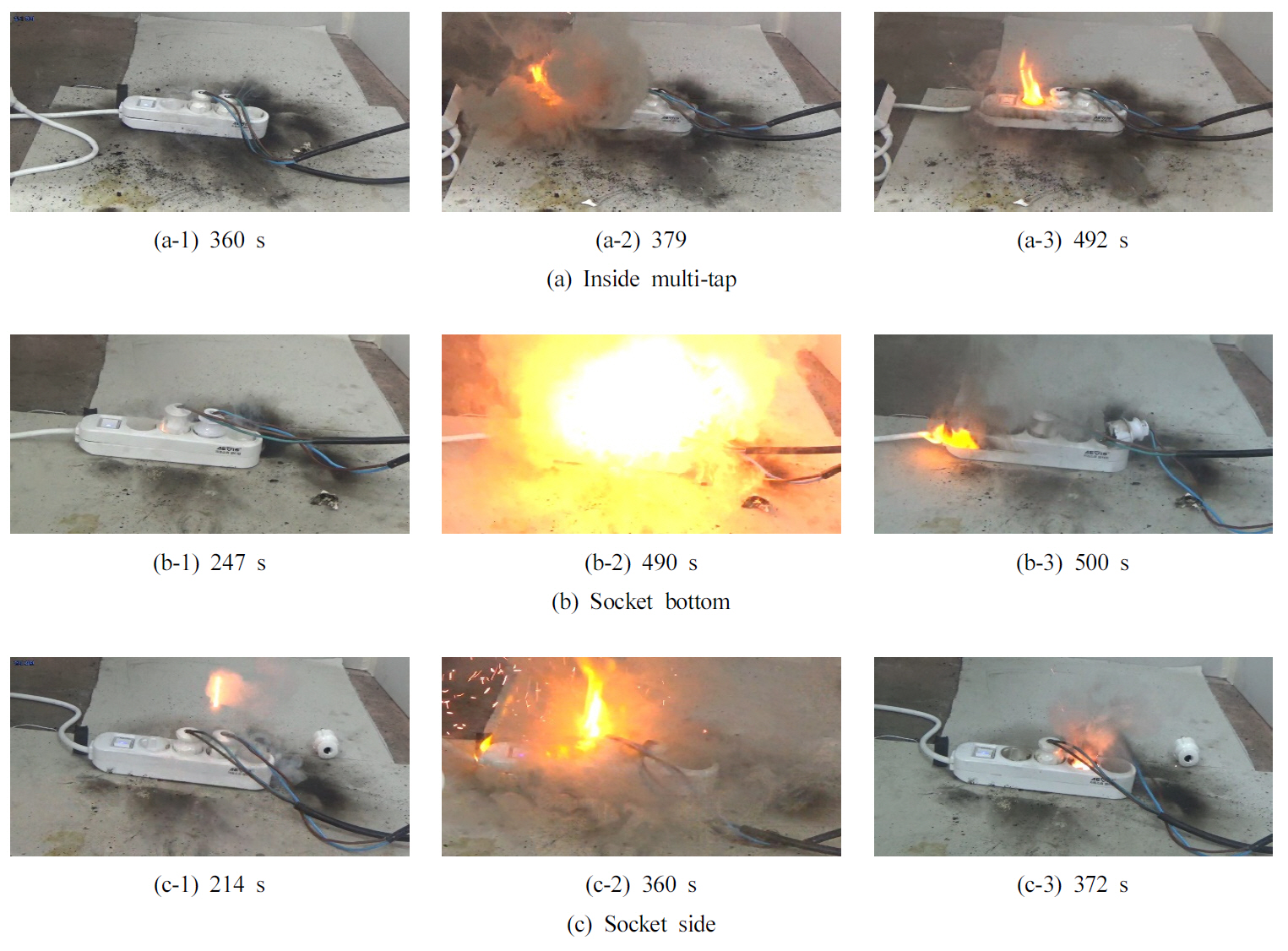
Figure 9 shows the effects of the patch position on the fire extinguishing ability. Figure 9(a) presents the results of the multi-tap internal fire extinguishing patch experiment. The results show that there was no reaction until just before the third administration of saltwater (360 s). Nineteen seconds after the third administration (379 s), flames occurred instantaneously, but were extinguished immediately. A strong flame discharge occurred 12 s after the fourth administration (492 s), power was not applied due to a disconnection of the track, and the internal combustibles caught fire, but were extinguished within 2 s. Figure 9(b) shows the results when the patch was placed at the socket bottom. After the second administration of saltwater, flame discharge occurred after 7 s (247 s), and the amount of smoke increased significantly from the third administration. Fire spurted out and strong flame discharge occurred, accompanied by an explosive sound, and the plug was pulled out 10 s (490 s) after the fourth administration. After 10 s (500 s), the fire continued to spread inside the multi-tap, but was terminated because no electricity was applied. Figure 9(c) presents the results when the fire extinguishing patch was placed on the side of the socket. After the first administration of saltwater, an explosive sound occurred after 94 s (214 s), and immediately after the third administration (360 s), continuous flame discharge and emission of fire were observed from the inside of the multi-tap. After 12 s (372 s), strong flame discharge occurred, the plug was pulled out, and the fire continued to spread; thus, the experiment was terminated.
Effect of internal combustibles on NAP.
Electrical devices, such as multi-taps or outlets, are continuously used without maintenance such as cleaning until a failure occurs, dust accumulates inside these devices due to such environmental characteristics, and the accumulated combustibles become a medium of fire due to various electrical factors. As a result, under the present experimental conditions, attaching a fire extinguishing patch to the inside of the multi-tap was found to be the optimal position for preventing multi-tap fires and minimizing fire damage. This is because when the fire extinguishing patch is attached to the inside of the multi-tap, the microcapsules of the fire extinguishing patch emit the fire extinguishing agent just before the flame is generated, with the accompanying heat rise, thereby vaporizing and releasing a large amount of the fire extinguishing agents in the multi-tap. Because the interior of the multi-tap is a relatively closed space, fire inside the multi- tap is suppressed by the cooling and suffocation effects.
5. Conclusions
To identify the effect of a microcapsule fire extinguishing patch on reducing electrical fires in a multi-tap, a complex electrical fire due to overload and tracking was simulated, and the effect of a fire extinguishing patch on reducing electrical fire under the same conditions was verified. Based on the results, the following conclusions were drawn.
(1) In the case of the samples without fire extinguishing patches, thick black smoke, along with white smoke, was generated at 1,180 s; flame discharge occurred due to the formation of a carbonization conductive path in the internal material; continuous flame discharge occurred at 1,187s; and short circuits caused by tracking occurred due to the growth of conductive tracks, with the generation of exposed flames. Moreover, temperatures exceeding the maximum measurement range of the thermal imaging camera (350 °C) were observed.
(2) In the case of the samples with fire extinguishing patches, overload was applied for 2,400 s considering the risk of the experimental equipment and the experiment. However, only white smoke generated by thermal decomposition of gas or internal combustibles was observed, due to the action of the fire extinguishing patch microcapsule, and no external risk characteristics were observed; the temperature increased to 115.8 ℃.
(3) Analysis of the damage characteristics inside the multi- tap showed that the samples without fire extinguishing patches generated exposed flames, resulting in carbonization and melting, and the degree of damage was quite severe. However, in the case of the samples with fire extinguishing patches, carbonization occurred in the power line socket region, but no flame occurred due to the release of the fire extinguishing agent stored in the microcapsule.
(4) Analysis of the effect of the location of the fire extinguishing patch confirmed that attaching it to the inside of the multi-tap is the optimal positioning for preventing electrical fires in the multi-tap and minimizing fire damage.
The effect of the microcapsule fire extinguishing patch on reducing electrical fires in the multi-tap was investigated under the experimental conditions described above. Although fire may not occur in certain scenarios, various conditions and variables can work in conjunction to achieve the worst state, which can eventually lead to a fire. Thus, if long-term conditions are reflected, the fire extinguishing patch cannot prevent all multi-tap fires. However, there is currently a lack of appropriate measures to prevent multi-tap fires, given that a fixed fire extinguishing system cannot be used because the multi-tap is employed in variable environments, and there is a limit to arranging fire extinguishers for each multi-tap. Therefore, at present, fire extinguishing patches are considered the best alternative for minimizing fire damage during multi-tap electrical fires, where facilities vulnerable to multi-tap electrical fires, such as distribution centers and factories, need to have an institutional arrangement to make it mandatory to install fire extinguishing patches for preventing multi-tap fires.
Notes
Conflict of Interest
The authors declare no conflict of interest.