
1. Introduction
Environmental regulations have become restrictive to motor vehicles worldwide to achieve the goal of reducing carbon dioxide and greenhouse gas emissions. Accordingly, a series of national policies providing benefits to owners of green cars, such as plug-in hybrid electric vehicles (PHEVs), battery electric vehicles (BEVs), and hydrogen fuel cell electric vehicles (FCEVs), have been consistently announced in South Korea; this is expected to guide the transition toward zero-emission vehicles. According to the 4th national plan on green cars proposed in February 2021, the Korean government anticipates that electric vehicles will account for 51% of the new passenger car market share in 2025 and 83% in 2030, resulting in the removal of 24% of the carbon dioxide emissions generated from motor vehicles by 2030 [1]. The market share of green cars among all Korea-registered passenger cars has rapidly increased from 0.7% in 2014 to 4.1% in July 2021, and the number of registered cars has exceeded 1 million.
The market share of FCEVs is not as large as that of BEVs; 17,552 FCEVs were registered in Korea by November 2021, which is equivalent to 9% of BEVs (approximately 200,000 BEVs were registered by September 2021). In addition, no incidents of fire or explosion related to FCEVs have been reported to date. However, doubts still exist regarding the fire safety of FCEVs under accidental circumstances as the recently developed vehicles are powered by a different system from that of conventional internal combustion engine vehicles (ICEV) and are thus unfamiliar to the public. As FCEVs particularly involve hydrogen storage vessels (HSVs) with at least 70 MPa pressure, researchers have examined the risk of HSV explosion at elevated temperatures [2-4]. Most studies have used LPG burners to heat HSVs (i.e., Bonfire test), focusing on observing variations in internal pressures of HSVs with increasing temperatures and their explosive behaviors under different test conditions. A full-scale fire test was also performed on FCEVs to understand the development of fires [5]; two type-3 HSVs at 35 MPa were mounted on an ICEV's trunk to represent FCEVs, and an ash tray in the specimen's driving seat was ignited. A rapid flame spread was observed in an ICEV filled with gasoline, while less fire damage and shorter combustion duration were identified in the HSVs-mounted ICEV, even though a dangerous hydrogen-jet-flame released from a thermally activated pressure relief device (TPRD) of the HSVs was observed.
In addition to the prior efforts to understand the capability of HSVs to resist fires or explosions, further studies are needed on (i) the potential fire load of FCEVs, (ii) the behavior of internal flame spread throughout FCEVs, (iii) the degree of thermal impacts originating from an FCEV's internal fire on the HSVs installed at the bottom of vehicles and the high-voltage lithium-ion batteries (LIB) placed in the trunk, and (iv) the degree of thermal damage on objects adjacent to the heat source (i.e., an FCEV fire), such as parked cars and upper structural members of underground spaces, multi-story parks, and tunnels. To evaluate the aforementioned topics in this study, a 10-MW-scale cone calorimetry and a test rig equipped with thermocouples and heat flux gauges were utilized in full-scale fire testing. Note that TPRDs were removed from HSVs to deliberately release hydrogen prior to testing as the assessment of the HSVs' explosion hazard or behavior is beyond the scope of this work. All time-dependent measurements, such as temperature, heat flux, and visual image, were analyzed within an identical timeline to comprehensively interpret the behavior of the FCEV fire.
2. Experimental
2.1 Overview
Unlike conventional ICEVs, FCEVs are powered by a fuel cell stack (FCS) that generates electric energy from hydrogen. FCSs are generally installed at the front of the vehicle, as illustrated in Figure 1(a). Three units of 70 MPa HSV capable of holding 52.2 L of hydrogen were mounted in the rear region under the trunk, as shown in Figure 1(b). In addition, 64 LIB cells with a total energy capacity of 1.56 kWh were placed immediately above the HSVs in the trunk, as shown in Figure 1(b). Table 1 lists the critical specifications of the FCEV used in the test.
2.2 Test conditions and measuring data
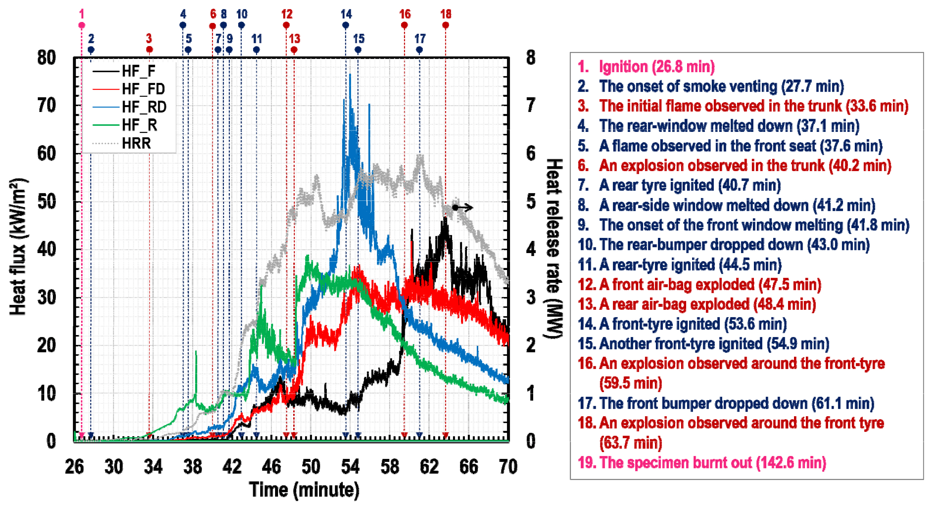
In this study, a full-scale fire test was conducted to quantitatively analyze the risk of FCEV fires. Both the heat release rate (HRR) and total heat released (THR) of the FCEV sample were measured using large-scale cone calorimetry, as shown in Figure 2(a). Time-dependent temperature profiles of the combustion products were measured using k-type thermocouples (TC_x) installed in a customized test rig, as shown in Figures 2(b) and 2(c), which can be used to estimate the potential thermal damage to the upper structural members of underground spaces, multi-story parks, or tunnels. The thermocouple positions can be categorized into two groups with respect to their heights: the upper group with a 2,270 mm height (TC_GB, GW, GR, and GCRW) and the lower group with a 1,270 mm height (TC_GFW and GRW) above ground level to measure the temperature of gases above the vehicle's overall height and venting through its windows, respectively. Four Schmidt-Boelter gauges (HF_F, FD, RD, and R; Model: SBG01, Hukseflux Thermal Sensors BV) were installed in the test rig to estimate irradiance on the exposed surfaces of vehicles adjacent to the origin of fires, and the gauge positions were determined in accordance with the Korean standard on adequate dimensions of a parking lot, as shown in Figure 2(d). Finally, to observe the behavior of the flame spread throughout the passenger cabin, a group of thermocouples was positioned within the cabin, as illustrated in Figure 2(e). It should be noted that the end tips of all the thermocouples were not allowed to contact any objects, but were securely fixed at designated points so as not to fluctuate owing to fluid motions, as the sensors intended to measure gas temperatures. A data acquisition system was used to collect the data at a frequency of 10 Hz. Table A1 lists the sensor types, positions, and abbreviations used.
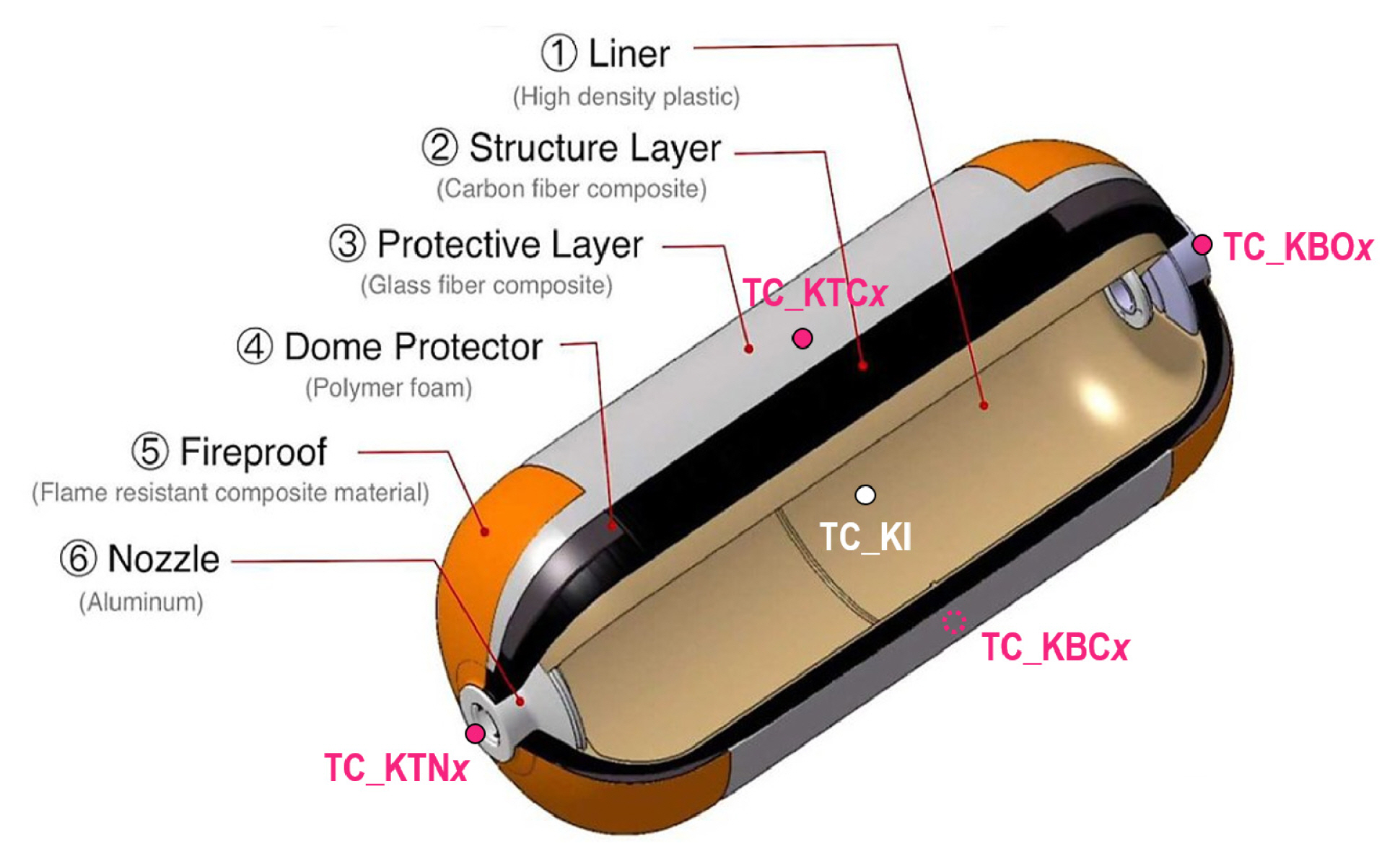
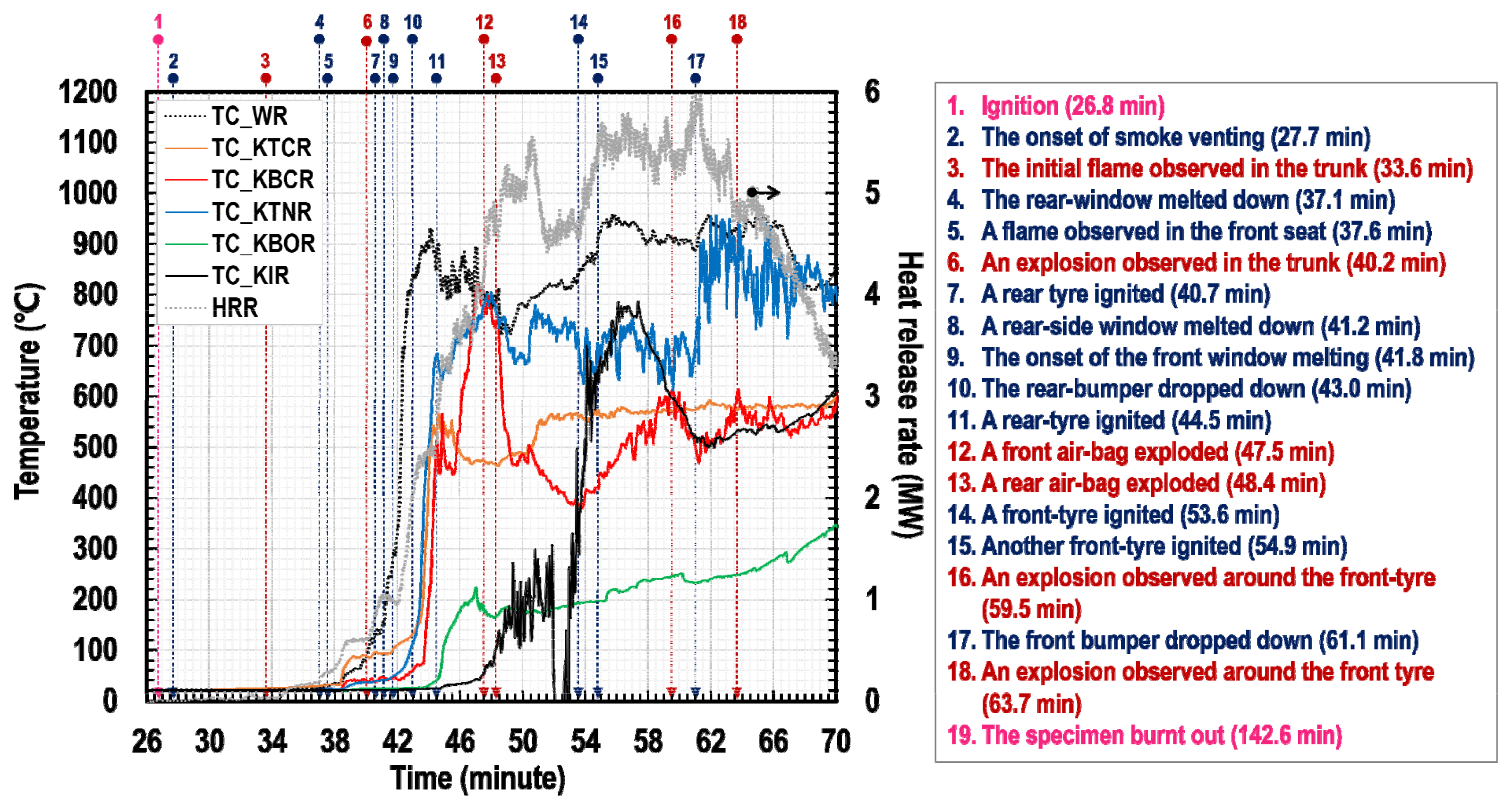
In addition to the measuring factors typically collected in full-scale car fire tests, HSVs and LIBs, which reveal the different features of FCEVs and conventional ICEVs, were fitted with thermocouples to estimate the degree of thermal impact on these potentially dangerous substances. Five thermocouples were attached to the nozzle (TC_KTNx), boss (TC_KBOx), upper-middle (TC_KTCx), and lower-middle (TC_KBCx) of each HSV, as shown in Figure 3. For health and safety reasons, TPRDs were physically removed from the HSVs, thereby deliberately discharging the high-pressure hydrogen gas stored in the vessels before testing. Table 2 lists the specifications of the type-4 HSVs used in the test.
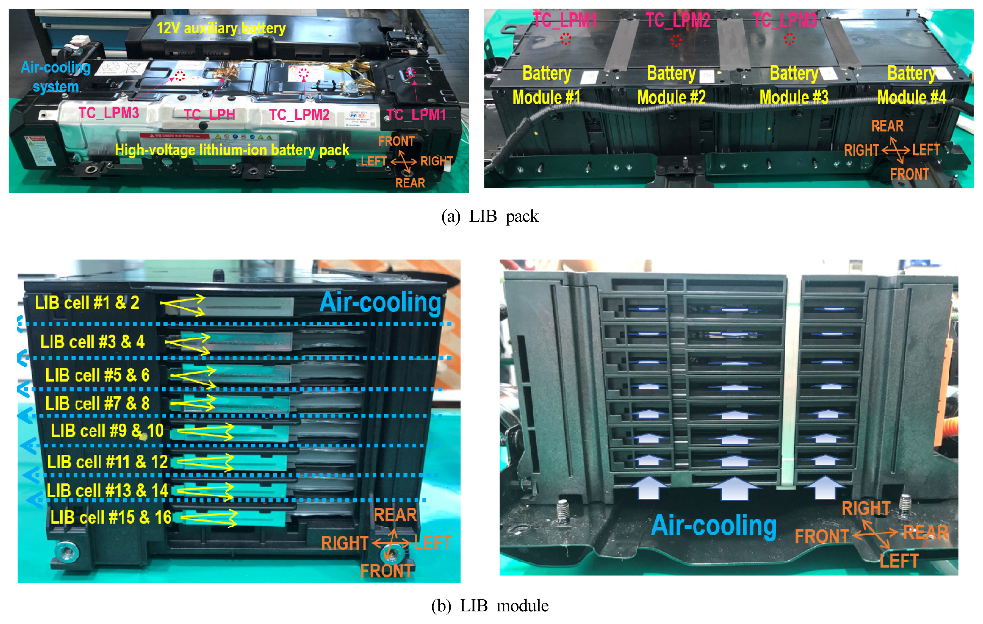
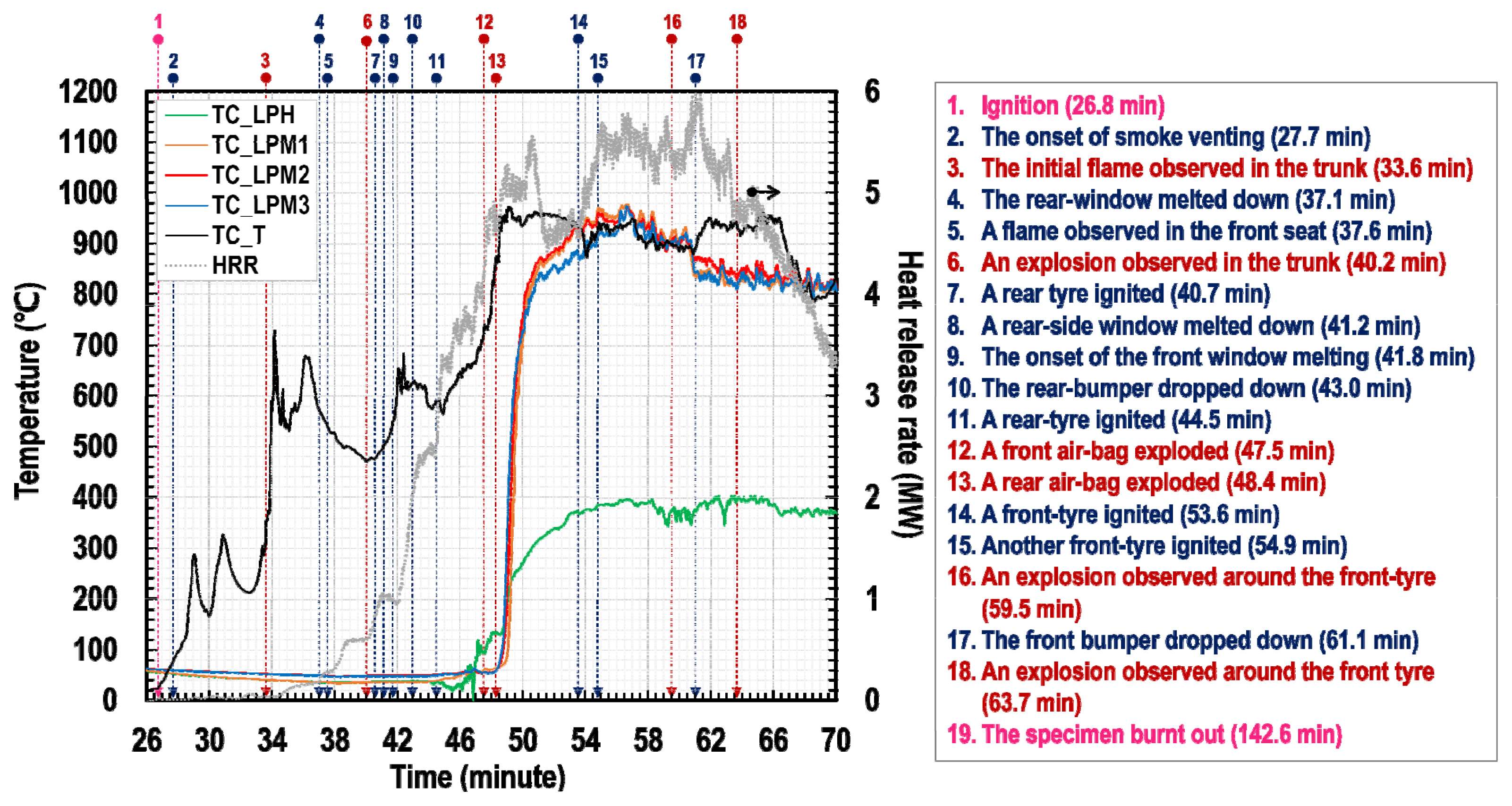
The high-voltage LIB pack mounted on the FCEV trunk is adjacent to the 12 V auxiliary battery and is composed of four modules (#1-4), as shown in Figure 4(a). The LIB pack was disassembled into modules to recharge and install thermocouples on the surfaces of the LIB cells (TC_LPM1-3) and pack-housing (TC_LPH). Each LIB module was composed of 16 pouch-type cells, as shown in Figure 4(b). The cells are spatially distant from each other enabling air flow to prevent overheating of LIBs. The orange marks in Figure 4 are intended to guide the understanding of the directions of the object in the figures, which depict the directions of the vehicle.
The FCEV, which adopts hydrogen as a fuel, is powered by an electric motor that consumes electrical energy generated by FCSs and stored in LIBs. The capacity of the FCEV's LIBs is 1.56 kWh which is relatively low compared with those of contemporary BEV LIBs with a 50-100 kWh capacity. In addition, as mentioned in the previous paragraph, an air-cooling system operates through the spaces between LIB cells. Therefore, the possibility of thermal runaway due to insufficient heat dissipation is likely to be low. However, there still exists the possibility of manufacturing defects in LIB cells leading to subsequent ignition with thermal runaway in the area of the trunk, or the possibility of the thermal runaway of LIB cells being triggered by a flame spread ignited from the passenger cabin. Considering such possibilities, a scenario of ignition in the trunk was attempted (i) to observe the flame spread behavior toward the passenger cabin and other parts based on the assumption of a fire initiated at LIBs in the trunk and (ii) to understand the duration it takes for the LIB temperature to reach a critical point of thermal runaway under the condition of a trunk fire. A round metal pan 200 mm in diameter, filled with 50 ml n-heptane, was mounted around the LIB pack on the vehicle's trunk to activate the ignition scenario.
Finally, an oxygen consumption principle-based large-scale cone calorimeter was used to quantitatively evaluate the hazards of FCEV fires by measuring the thermal energies generated from the combustion products of the FCEV. Approximately 25% of the total window areas of the car's left-front and rear seats were opened to allow air circulation during the test for an adequate combustion environment. In addition, the location of the FCEV sample in the test site was regulated under the exhaust hood to collect most gaseous products released from the burning car for better measurements of the HRR and THR.
3. Results and Discussion
3.1 Heat release rate and total heat released
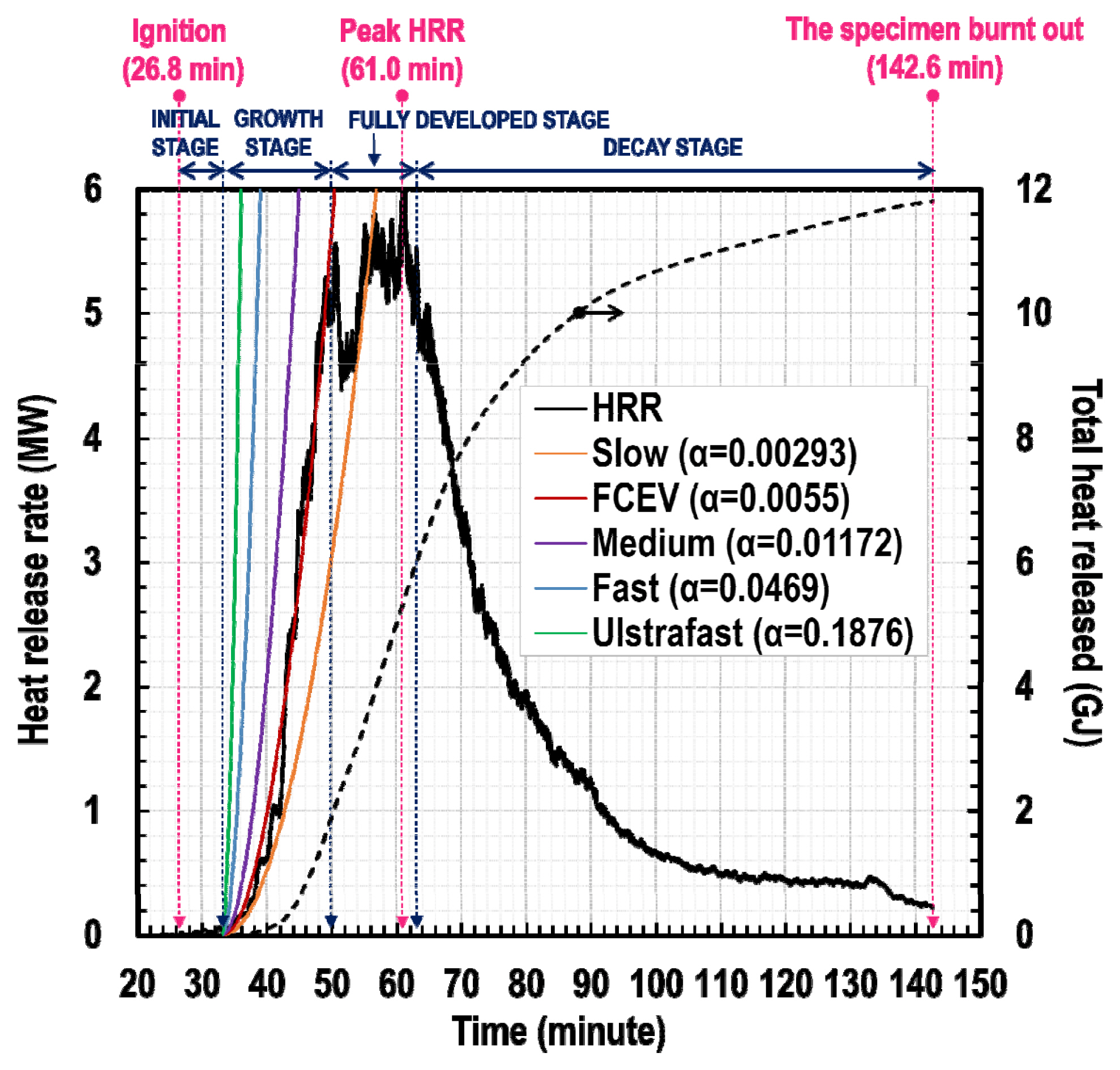
The large-scale cone calorimetry utilized in this study measures the HRR and THR of combustion gas based on the experimental data of general hydrocarbon combustions; approximately 13.1 MJ of thermal energy is yielded per unit mass of oxygen consumed [9]. Figure 5 shows the variations in HRR and THR of the FCEV with time. To understand the degree of the FCEV fire growth, the concept of t-squared fire growth curve, which is conventionally used in fire safety engineering, was adopted, wherein the development of the HRR during a fire growth stage is mathematically expressed by a power law, as formulated in Eq. (1):
where Q ˙
n-Heptane was ignited 26.8 min after the onset of measurement data. The FCEV fire gradually developed for approximately 23.2 min and its growth rate was between 'slow' (╬▒ = 0.00293 kW/s2) and 'medium' (╬▒ = 0.01172 kW/s2), resulting in ╬▒ = 0.0055 kW/s2. The fire attained the fully developed stage at around 50 min and recorded its peak heat release rate (pHRR) at 5.99 MW around 61.0 min; it took approximately 34.2 min from the ignition to the point. The fully developed fire was maintained for approximately 13.2 min and later transitioned into the decay stage; it took approximately 36.4 min from the ignition to the end of the fully developed stage (or the onset of the decay stage). The FCEV fire gradually decayed over approximately 80 min. At 142.6 min when data acquisition was stopped, small burning fragments were still observed. However, the amount of combustion gas produced was too small to be measured by the large-scale cone calorimeter; thus, the state of the vehicle was considered to be fully burnt out. The amount of the heat accumulated (i.e., THR) was approximately 11.8 GJ at the instant. In this regard, according to a study[10] which reviewed 41 full-scale car fire tests performed between the 1980s and the end of 2000s, the values for the averaged pHRR and THR of medium-sized passenger ICEVs with 1380-1587 kg in curb weight were 6.8 MW and 6.4 GJ, respectively. The pHRR of the FCEV obtained in this work was comparable with that of the ICEVs from previous tests, while the THR measured in this study was greater than that obtained in the past. This is related to the increase in the amount of polymeric interior materials used in the present FCEV compared with those applied in the ICEV models released in 1970-1999.
3.2 Flame behavior
3.2.1 Initial stage
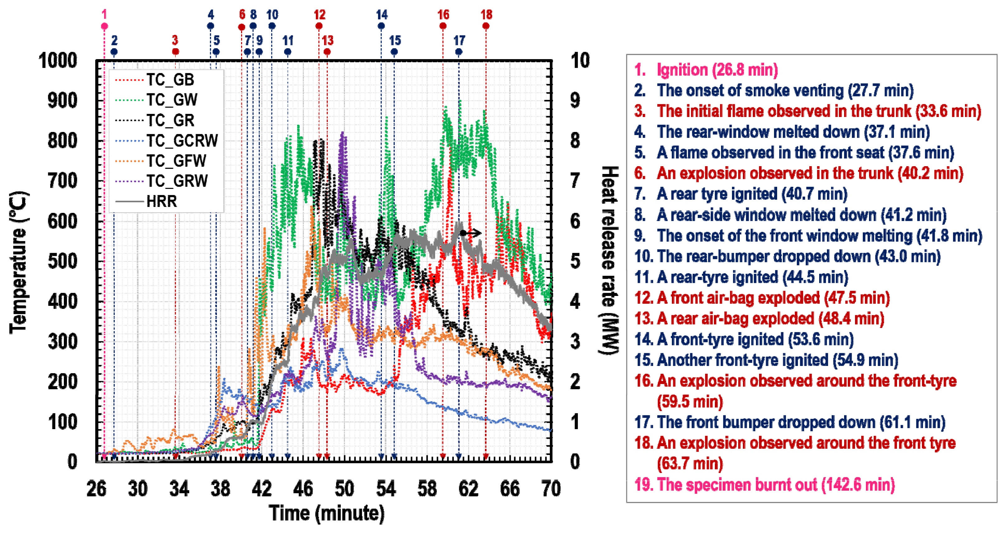
The flame behavior was examined by observing the temperature-time profiles obtained from the thermocouples installed in the test rig and at the major parts of the FCEV. Figure 6 shows the gas-temperature variations with time at several points within the passenger cabin, where the numbers with arrows marked at the top of the graph indicate the temporal instants of the major events observed from measurements and visual images along the timeline, which are listed on the right-side of the graph. The ignition of n-heptane (#1) was initiated at 26.8 min on the trunk on which the LIB pack was mounted. A small amount of light gray smoke was observed through the driver's window 27.7 min onwards (#2), while a flame was first observed outside the trunk at 33.6 min (#3). Although the gas temperature within the trunk (TC_T) exceeded 300 ┬░C, the amount of combustion gas was less; thus, the HRR measured using the calorimeter was low. The initial stage of an FCEV fire can be defined from the onset of ignition to this instant, as shown in Figure 5.
3.2.2 Growth stage
After the initial stage, the internal fire in the regions of the trunk (TC_T) and rear seats (TC_CRS) stagnated at approximately 600 ┬░C for 3-4 minutes, and began to regrow rapidly due to an inflow of air through the melted and broken rear window at 37.1 min (#4), so that the local temperature (TC_CRS) increased to approximately 700 ┬░C, as shown in Figure 6. At 37.6 min (#5), the gas temperatures at the front seats (TC_CRS) and dashboard (TC_CD) also increased rapidly, owing to the robustness of combustion in the upper space within the cabin. At 40.2 min (#6), a small explosion was identified in the trunk, which was ascribed to the explosion of airbags near the rear seats. The flame gradually spread from the interior materials to the exterior coatings and led to the ignition of one of the rear tires at 40.7 min (#7). The side windows of the rear and front seats melted and failed at 41.2 (#8) and 41.8 (#9) min, respectively. Subsequently, air flowed in and out more fluently through the opening of the damaged windows, resulting in a more vigorous combustion of the interior materials. The fire finally reached the growth stage, as evidenced by the rapid increases in HRR, THR, and TC_Gx (Figure 7). Other airbag explosions were identified around the front and rear areas at 47.5 (#12) and 48.4 (#13) min, respectively. The next stage (i.e., the fully developed stage) was estimated to reach approximately 50 min, as described in Figure 5, based on the observation of the rapid increase in temperatures on the cabin floor (TC_CRF), indicating the burning of the entire interior materials.
The flame spread to the exterior coatings in the growth stage began damaging the external parts of the vehicle; the rear bumper failed at 43 min (#10), and the rest of the rear tire ignited at 44.5 min (#11). At this moment, air naturally flowed in and out through the trunk area, and the temperature in the trunk (TC_T) was sufficiently high to ignite all the interior materials, as shown in Figure 8. Under these conditions, the temperature of the LIB-pack metal housing (TC_LPH) began to increase. However, the ignition of LIB cells was delayed for a few minutes because of the high thermal capacities of the metal and plastics surrounding the LIB cells. Most of the LIB modules were simultaneously ignited for approximately 49 min. Their temperatures (TC_LPM1-3) increased rapidly beyond 800 ┬░C, and the metal housing with a high thermal capacity was subsequently heated to 100 ┬░C in an instant. These observations support the occurrence of thermal runaway in LIBs.
3.2.3 Stages of fully developed and decay fires
During the fully developed stage (50-63.2 min), the gas temperatures within the passenger cabin and above the vehicle remained around 1,000 ┬░C, as shown in Figure 6, and 800 ┬░C, as shown in Figure 7. At 53.6 (#14) and 54.9 (#15) min, the front tires individually ignited. The flame spread throughout the exterior coatings negativity affected the front bumper, leading to failure at 61.1 min (#17). At this stage, the median and peak values for incident heat fluxes on the gauges were 27.2 and 76.5 kW/m2 respectively, as shown in Figure 9, and were capable of igniting adjacent combustibles. Critical heat fluxes to gypsum boards, polyurethane foams, and wood were addressed as 35, 20, and 12 kW/m2, respectively [11]. In this regard, further studies can offer an understanding of the duration it takes the 27.2 kW/m2 irradiance to ignite recipients, such as exterior coatings, windows, and interior materials of adjacent cars visible through windows. It is important to be aware of the degree of peak irradiance (76.5 kW/m2), which is close to that of a flash fire; this phenomenon represents a life-threatening hazard to responders, and its intensity (84 kW/m2) is conventionally used to evaluate the thermal protective performance of firefighters' garments [12]. In addition, small explosions were observed intermittently during the fully developed and decay fire stages (59.5 (#16) and 63.7 (#18) min, respectively). Based on the temperature-time profiles obtained in this study, it can be anticipated that if an FCEV fire occurs indoors (such as underground spaces, multi-story parks and tunnels), the fire plume at 800 ┬░C could at least impose thermal damage on upper structural members (such as ceilings, beams, and girders) for approximately 13 min; further study is needed to understand the decrease in the strength of structural members due to such thermal damage.
3.2.4 High-pressure hydrogen storage vessel (HSV)
As the combustion gas generated from the FCEV fire was supposed to be forcibly exhausted through the hood by the gas collection facility of the large-scale cone calorimeter, the gas produced in the initial stage was incapable of thermally impacting the HSVs located underneath the FCEV's trunk, as shown in Figure 10: small increases in temperatures of HSVs were observed until the middle of the fire growth stage (approximately 41.8 min (#9)). The temperatures of HSVs increased sharply after the rear bumper failed at 43 min (#10), and the rear tires ignited at 40.7 (#7) and 44.5 (#11) min. Note that TPRDs installed in HSVs are designed to open their valves to discharge the pressurized gas at 110 ┬░C to prevent explosions. Considering the temperature changes of the TPRDs (TC_KTNx), it can be predicted that the high-pressure hydrogen gas would be sequentially discharged through the TPRD valves in the rear, middle, and front vessels.
Type-4 HSVs are composed of a glass fiber/epoxy composite protective layer, carbon fiber/epoxy composite structure layer, and high-density polymer liner, as shown in Figure 3. As polymers among composite materials are flammable, it becomes critical to consider their thermal properties from the fire safety perspective. In this regard, the decomposition reaction of the components of HSV proceeded in a sequence of epoxy resin, liner, and carbon fiber [3]. In a previous study, although thermogravimetric analysis (TGA) was affected by test conditions such as air or nitrogen atmospheric environments and mechanical stress, the first reaction typically began in the range of 220-300 ┬░C and recorded the peak rate of mass loss around 350 ┬░C. The second reaction, activated in a nitrogen atmosphere, started at 380 ┬░C and ended at approximately 480 ┬░C. The last decomposition of carbon fiber was reported as a less reactive reaction, which showed only 0.8% mass loss even at 800 ┬░C [13].
Utilizing the information on the thermal properties of the components of HSVs, the temperature-time profile of HSV#3 (i.e., TC_xR) was analyzed, as shown in Figure 11. HSV#3 began heating with the ignition of the rear tire (TC_WR), and the temperature of its nozzle part closest to the tire increased most rapidly. It is believed that the glass fiber/epoxy layer, which is the crust of the HSV, was simultaneously heated beyond 350 ┬░C, indicating that combustible gases might have been produced through thermal decomposition and subsequent ignition. This phenomenon resulted in a rapid increase in the temperature of the relevant areas (TC_KTCR and TC_KBCR) to approximately 550 ┬░C. Subsequently, a flame resulting from the ignition of the lower area of the HSV (TC_KBCR) decomposed the protective and structural layers, leading to a larger flame wherein the temperature increased to 800 ┬░C. The temperature of the metal boss of the HSVs slowly increased as compared to those of the other parts owing to its high thermal capacity. The internal temperature of TC_KIR began to rise at 47.5 min when the external polymeric layers were vigorously combusted. It is suggested that the combustion of the epoxy which bonded the glass fiber and carbon fiber layers together resulted in the creation of internal gaps, and the flames penetrating through these gaps caused the liner to decompose at approximately 54 min.
4. Conclusions
In accordance with the global trend of reducing carbon emissions, the supply of eco-friendly hydrogen fuel cell electric vehicles (FCEV) has been gradually expanding in South Korea. As these vehicles comprise high-pressure hydrogen storage vessels (HSV) and a new power system with a fuel cell stack (FCS) and lithium-ion batteries (LIB), this study quantitatively analyzed the fire hazard by physically measuring several parameters in a full-scale car fire test. A large-scale cone calorimeter was used to measure the heat release rate (HRR) and total heat released (THR) for the full-scale vehicle. The customized test rig was designed to simultaneously understand the variations in gas temperatures and heat fluxes at several positions. The conventional fire development process was adopted for analyzing the data obtained from the FCEV fire. The thermal damage originating from the passenger cabin fire on the HSVs and LIB pack was also examined.
The growth stage of the FCEV fire began approximately 10.3 min after the ignition of n-heptane in the vehicle trunk. The fire growth rate (╬▒ = 0.0055 kW/s2) was between 'slow' (╬▒ = 0.00293 kW/s2) and 'medium' (╬▒ = 0.01172 kW/s2), based on the principle of the t-squared fire growth curve. Major combustion initiated approximately 4.7 min after the start of the fire growth stage, whereas the thermal runaway of LIBs occurred 11.9 min after the onset of the stage. The temperature of the combustion gas at the top of the vehicle increased to approximately 800 ┬░C. The fully developed stage of the FCEV fire was attained 23.2 min after the ignition point, and the internal temperature of the vehicle stagnated at approximately 1,000 ┬░C during this period. The peak HRR and THR of the FCEV fire were measured to be 5.99 MW and 11.8 GJ, respectively.
Based on the experimental data, it can be predicted that if an FCEV fire occurs indoors (such as underground spaces, multi-story parks, and tunnels), a median heat flux of 27.2 kW/m2 and peak intensity of 76.5 kW/m2 could be imposed on the cars parked near the heat source, and flames at 800 ┬░C could also cause thermal damage to ceilings, beams, or girders for approximately 13 min. Major increases in the temperatures of the HSVs began when the flame propagated to the tires. Considering 110 ┬░C as the threshold temperature of TPRDs for pressure release, it can be predicted that high-pressure hydrogen gas could be discharged from the three vessels 16.2-26.2 min after the ignition point, assuming a normal operation of the device. The measurements obtained from this work can contribute to further studies on several topics, such as the behaviors of FCEV fires in various spaces and emergency response measures to FCEV fires.