Necessity of Protective Coordination Systems According to Battery Capacity
Article information
Abstract
As the capacity of lithium-based batteries rapidly is increasing, the number of applications using them is continuously increasing. However, this leads to the risk of fire and explosion, and thus, the number of accidents is increasing. To analyze the magnitude of short circuit currents according to the battery capacity and external circuit impedance and the necessity of protective coordination, this study conducted experiments using cylindrical batteries with capacities of 800, 2200, 3000, and 5000 mAh and cables with an impedance of 0.1Ω/m. Results indicated that as the battery capacity increased, the short circuit current increased and circuit-opening time decreased. However, as the circuit impedance increased, the short circuit current decreased and circuit-opening time increased. Based on these results, we reviewed protective systems applied to batteries and analyzed their problems. For protective systems designed considering the maximum short circuit current, if the state of charge is low or the impedance is high at the point of short circuit, the protective system does not operate when short circuit occurs, thus failing to block the circuit and potentially leading to fire. Therefore, while designing protective systems, it is appropriate to use multiple circuit breakers and fuses, considering the short circuit current according to the battery capacity and circuit impedance to enable protective coordination between devices.
1. Introduction
In recent years, various systems using lithium-based batteries with a higher energy density per unit area than those of lead-acid batteries are being operated. They are used in energy storage systems (ESSs) applied to renewable power generation systems, E-mobility (electric vehicles, bicycles, scooters), aerospace, and home appliances[1–3]. Regulations stipulate that an energy storage system (ESS) must be installed in the buildings of public institutions with a minimum contracted power of 1000 kW[4]. Though lithium-based batteries possess high energy density per unit area and have high utility, they introduce risks of fire and explosions leading to accidents; thus, they require preventive measures[5].
Depending on the battery-applied field, tests are conducted according to relevant regulations and standard procedures; these include external short circuit, impact, drop, thermal abuse, overcharge, internal short circuit, and thermal runaway propagation tests[6]. A basic protection method in a battery-applied system is to limit the occurrence of overcharge and overdischarge of the battery itself or isolate the circuit from the battery in the case of faults using a circuit breaker or fuse. The former method prevents problems occurring inside batteries in the case of overcharge and overdischarge, and the latter method uses circuit breakers and fuses to solve problems occurring in external circuits. Xiong et al. reviewed the diagnosis and prediction of short circuits in electric vehicle batteries. Short circuits in the internal and external circuits of a battery mainly cause fire-related accidents, and researchers indicated that the probability of the occurrence of internal short circuits is more than that of external short circuits[7]. For safe battery design, Conte et al. explained a measurement method and the fault path of the current generated in a short circuit; moreover, they explained that the short circuit current increases with an increase in the battery capacity[8]. Figure 1 shows the major causes of internal and external short circuits in batteries. The major causes of internal short circuits include overcharge and overdischarge, battery manufacturing defects, external shocks, and internal heat generation. The major causes of external short circuits include insulation degradation, insulation damage, incorrect wiring, temperature rising, and fire. When a short circuit occurs in a battery, the magnitude of the short circuit current may vary with the internal impedance and state of charge (SOC)of the battery. When a short circuit occurs in an external circuit, the magnitude of the short circuit current is determined based on the SOC of the battery, the impedance of the internal and external circuits, and the point where the short circuit occurred[9–13]. In other words, at points closer to the battery, the external impedance decreases, thus increasing the short circuit current. Though researchers have proposed various measures to prevent short circuits inside batteries from developing into fire, this cannot be prevented from the source. In an external short circuit, a protective system (overcurrent circuit breaker, fuse, and protective relay) is applied to isolate the circuit from the battery to prevent it from developing into fire. However, in application systems using batteries, unlike general power systems, the magnitude of the short circuit current may vary with the capacity or SOC of the battery. As such, a protective coordination system applying instantaneous and time delay factors considering these characteristics should be used.
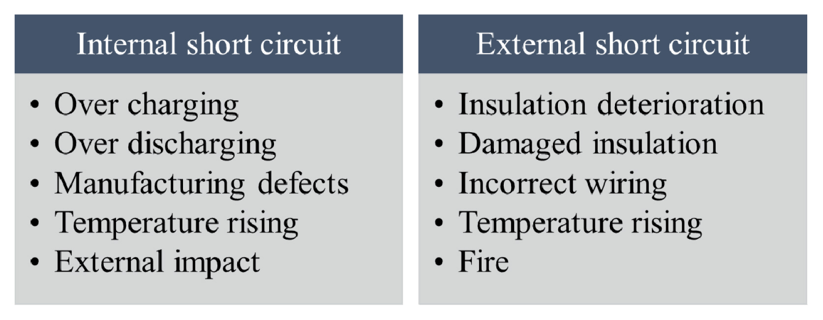
Causes of short circuit in lithium-based batteries.
This study analyzed the fault current magnitude according to changes in battery capacity and impedance and the suitability of protective systems, e.g., circuit breakers and fuses. Based on the results, the necessity of primary and secondary protective coordination systems was suggested.
2. Short Circuit Current and Protective Coordination System
2.1 Theoretical value of short circuit current
Figure 2 presents the basic circuit configuration of a battery-applied system. The configuration is divided into the battery and external circuit. The electromotive force (EMF: E) and internal resistance (Ri) of the battery are depicted. The external circuit comprises a fuse to block overcurrent, line impedance: R + XL, and load: RL. Eq. (1) defines the short circuit current when a short circuit occurs inside the battery. The current generated when a short circuit occurs is determined based on the EMF and internal resistance of the battery. Isc indicates the internal short circuit current.
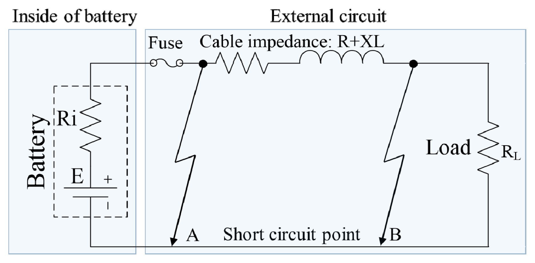
Circuit diagram of battery systems.
Eq. (2) defines the short circuit current when a short circuit occurs outside the battery. As indicated, an externally generated short circuit current may vary with the EMF and internal resistance of the battery and the point where the short circuit occurs. Iesc indicates the external short circuit current, EDrop denotes the line voltage drop, and RExternal denotes the external resistance.
Based on Eqs. 1 and 2, in Figure 2, the short circuit current at Point A is greater than that at Point B. Hence, if a short circuit occurs near the battery (power side), the value of the fault current increases.
Figure 3 shows the change in the short circuit current when the voltage and internal and external resistances of the battery increase. As shown in Figure 3(a), the internal resistance increases when a short circuit occurs inside the battery, which affects and decreases the short circuit current. Moreover, as the EMF increases, the short circuit current proportionally increases. This indicates that as the battery capacity and SOC increase, the short circuit current increases. As shown in Figure 3(b), when a short circuit occurs outside the battery, the resistance or impedance of the external circuit increases, thus decreasing the magnitude of the short circuit current. Therefore, when a short circuit occurs near the battery, the magnitude of the short circuit current increases, as it is less affected by the impedance of the external circuit, and as the distance from the battery increases, the short circuit current is affected by impedance.
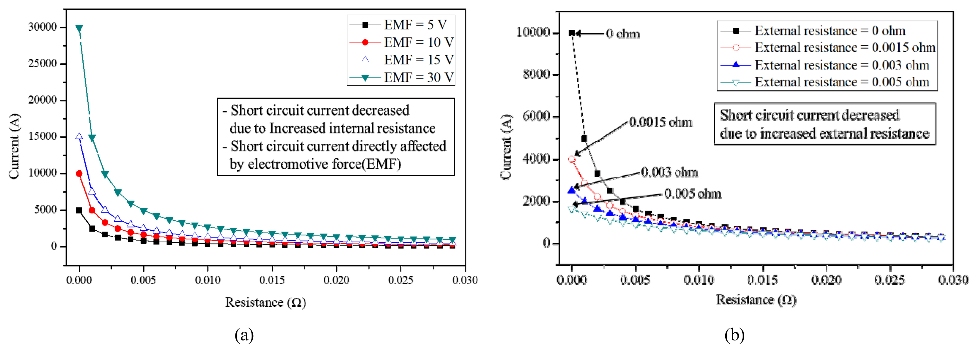
Short circuit current in a battery: (a) short circuit current directly affected by EMF and internal resistance (b) short circuit current decreased owing to an increase in the external resistance.
2.2 Protective coordination systems
When a fault (e.g., short circuit or ground fault) occurs in a power system, a protective coordination system operates to prevent the fault from propagating to other systems by quickly isolating the fault line from the system. To perform this protective function, the system is configured, so that relays can coordinate with each other. Relays, power fuses, and circuit breakers are used for protective coordination. Figure 4 shows the basic configuration of the time delay protection method. In the inverse time delay curve a, Ifb possesses a larger short circuit current than Ifa and a shorter blocking time. Hence, as the current generated at the time of the short circuit increases, the blocking time decreases. To protect Zone 1, circuit breakers trip according to the inverse time delay curve b, and to protect Zone 2, circuit breakers trip according to the inverse time delay curve a. If Circuit Breaker 4 in Zone 2 trips, the fault does not propagate to Zone 1. However, if Circuit Breaker 4 in Zone 2 does not trip, Circuit Breaker 1 in Zone 1 trips after a certain period of time to prevent the fault from propagating to the power system. Thus, protective coordination is performed between the circuit breakers in Zones 1 and 2. However, in the protection method for battery-applied ESSs and electric vehicles, individually applying fuses and circuit breakers tripped by overcurrent to the circuit may cause fire and other accidents.
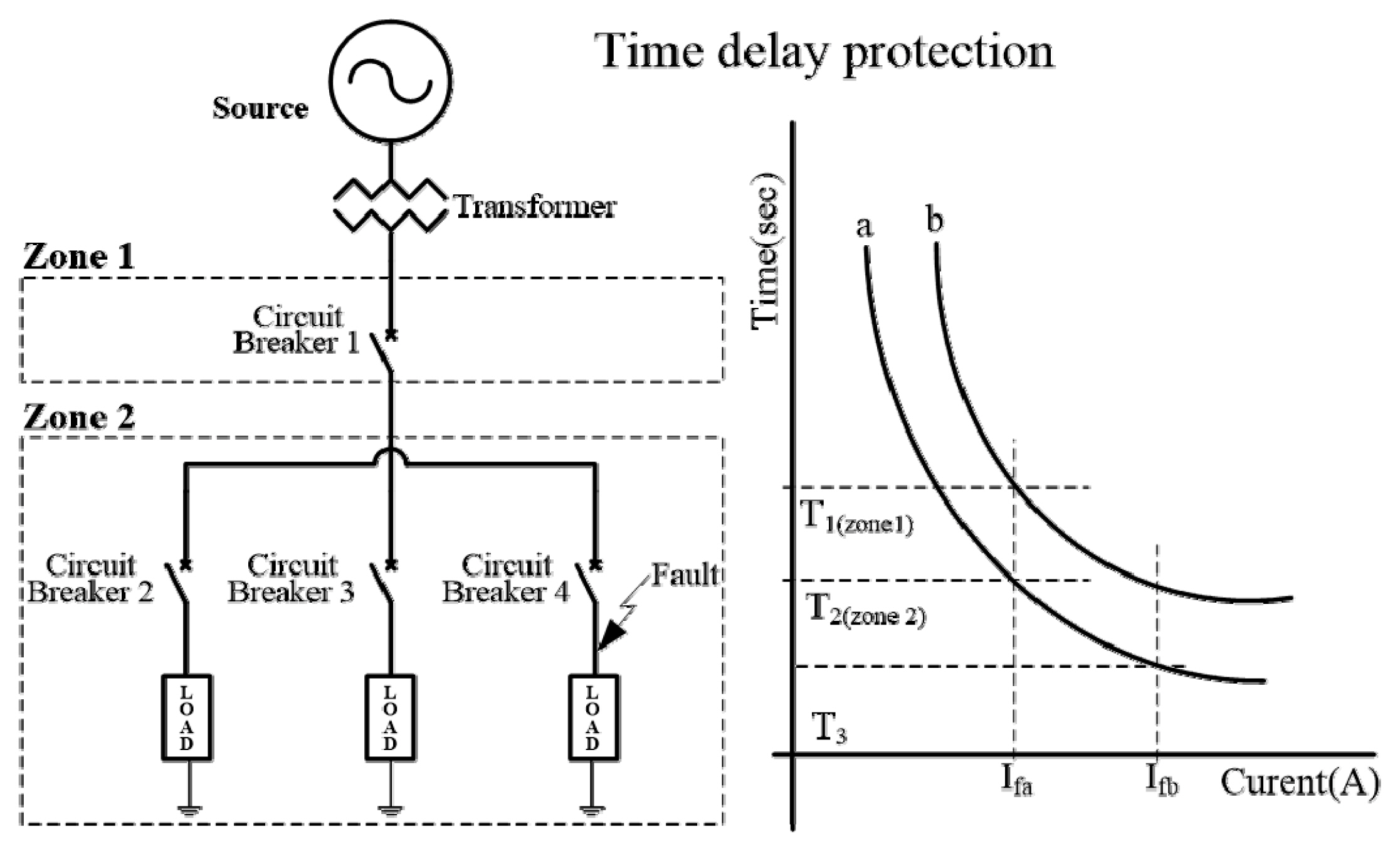
Protective coordination system.
3. Experimental Setup
Figure 5 shows the hardware configuration of the experiment. To verify the magnitude of the short circuit current according to capacity, 3.7 V 2.96 Wh (800 mAh), 8.14 Wh (2200 mAh), 11.1 Wh (3000 mAh), and 18.5 Wh (5000 mAh) cylindrical lithium-ion batteries were used. The experiment was performed without the protective circuit. In the short circuit current experiment, cables with impedances of 0.1, 0.2, and 0.3 Ω were applied to increase the line impedance. For the cable short circuit, a magnetic connector was used for on/off operations, and a shunt resistor was used to measure the current. To verify the increase in the temperature of the lithium-ion battery during short circuit, a K-type thermocouple was attached to the battery surface, and the data were measured using the data acquisition system and LabVIEW program of National Instruments.

Experimental setup.
4. Experimental Results
Figure 6 shows the test results of the short circuit current according to capacity. (a) 800 mAh, (b) 2200 mAh, (c) 3000 mAh, and (d) 5000 mAh. The maximum current and maximum temperature when the short circuit occurred are as follows: 800 mAh: 45 A, 64 °C; 2200 mAh: 60 A, 142 °C; 3000 mAh: 109 A, 125 °C; 5000 mAh: 149 A, 101 °C. At 800 mAh, the increases in the current, duration, and temperature with regard to the short circuit were limited; thus, internal damage to the battery and off-gases did not occur. At 2200, 3000, and 5000 mAh, after the short circuit test, faults occurred inside the batteries in an open state. Owing to the increase in internal pressure caused by the increase in temperature, off-gases were released from some test samples, though they did not transition to a thermal runaway state. Hence, when an external short circuit occurs, the magnitude of the short circuit current and duration may vary with the capacity and SOC of the battery, and the temperature increase is directly affected. Furthermore, in terms of fail-safe, the test results indicated that when a temperature of 100 °C or higher is continuously maintained, the current cannot flow through the circuit owing to the fault (open circuit) inside the battery.

Test results of short circuit: (a) 3.7 V, 2.96 Wh (800 mAh); (b) 3.7 V, 8.14 Wh (2200 mAh); (c) 3.7 V, 11.1 Wh (3000 mAh); (d) 3.7 V, 18.5 Wh (5000 mAh).
Figure 7 shows that the short circuit current proportionally increases as the battery capacity increases. While using large-capacity batteries in ESSs and automobiles, the magnitude of the short circuit current can vary from several to dozens of kA or more; thus, it is necessary to design cables, main components, and protective systems adaptable to the aforementioned conditions.
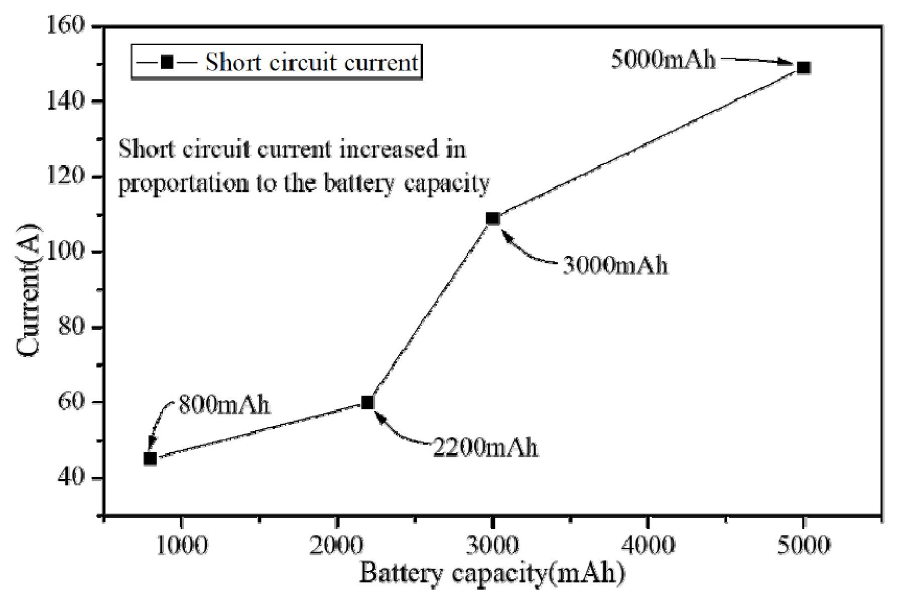
Short circuit current directly affected by the battery capacity.
Figure 8 shows the short circuit current according to changes in the impedance of the external circuit. The capacity of the battery considered in the experiment is 3000 mAh, and the impedance of the cable used for the external circuit is 0.1 Ω/m. The impedance of the external circuit is 0.1 Ω in (a), 0.2 Ω in (b), and 0.3 Ω in (c). When the impedance values of the external circuit were 0.1, 0.2, and 0.3 Ω, the short circuit current decreased to 41.8, 31.6, and 24.6 A, respectively. This indicates that the short circuit current decreases as the impedance of the external circuit increases. Immediately after the occurrence of the short circuit, the short circuit current becomes maximum and slowly declines owing to an increase in resistance caused by the increase in the temperature of the battery and external circuit. When the battery surface temperature ranged from 105 to 120 °C, internal breakdown occurred and the circuit opened, thus limiting the current flow. Figure 8(d) shows the correlation between the breakdown time and short circuit current as the external circuit impedance increases (as the point of short circuit moves away from the battery). As the impedance increases, the short circuit current decreases, thereby increasing the breakdown time. While this may vary in the battery-applied system, if a current lower than the operating currents of the circuit breaker and fuse flows after the occurrence of short circuit, the short circuit current may continuously flow in the circuit, thus potentially leading to fire.

Short circuit current caused by an increase in external impedance (a) line impedance: 0.1 Ω (b) line impedance: 0.2 Ω © line impedance: 0.3 Ω (d) breakdown time directly affected by line impedance continued.
As shown in Figure 9, the battery test results are applied to the trip curve of the 30 A wiring circuit breaker, which is used to block overcurrent in the circuit. The criteria for selecting a circuit breaker should be that the circuit breaker must be able to block the fault current, continuously carry the load current below the rated current, and not trip unnecessarily in cases other than accidents. If the battery possesses a large capacity or short circuit occurs near the battery, the magnitude of the short circuit current exceeds the tripping current of the circuit breaker; thus, there is no problem in protecting the circuit. However, if the battery possesses a small capacity or short circuit occurs far from the battery (increased external circuit impedance), the magnitude of the short circuit current falls outside the tripping zone of the circuit breaker. Therefore, in battery-applied systems, rather than applying one protective device, it is necessary to use circuit breakers and fuses that coordinate with each other, so that a fault occurring in the circuit does not propagate to the upper system (toward the battery).

Trip curve of a circuit breaker with experimental results.
5. Conclusions
This study analyzed the characteristics of short circuit currents according to battery capacity, external circuit impedance, and the necessity of protective device coordination. As the battery capacity increased, the magnitude of the short circuit current proportionally increased; as the external circuit impedance increased, the short circuit current decreased and the circuit-opening time increased. However, when a current of 100 A or more flowed due to an external short circuit, thermal runaway (battery ignition) did not occur despite the temperature rise inside the battery. If the battery capacity increases, the short circuit current increases; thus, the circuit breaker capacity may unavoidably increase as well. Consequently, the circuit breaker fails to trip when the SOC is low or the impedance of the external circuit is high. To solve this problem, multiple protective devices must be installed at appropriate points in the circuit and configured to perform protective coordination.
The number of application systems using batteries is continuously increasing, leading to an increase in the number of fire and explosion accidents. In recent times, it is difficult to preemptively prevent accidents, e.g., fires caused by faults that occur inside batteries. However, for faults that occur outside batteries, preventive measures with regard to protective device coordination are necessary to prevent faults from developing into fire events and enhance reliability.
Notes
Author Contributions
Conceptualization, methodology, and writing-original draft preparation, J. H. Kim; formal analysis, investigation, writing—review and editing, visualization, S.D.Kang., A.R.Min. Y.J.Park. and S.H.Kim. All the authors have read and agreed to the published version of the manuscript.
Conflicts of Interest
The authors declare no conflict of interest.