Analysis of Air Flow inside the Compartment under Backdraft Conditions using Solid Combustibles
Article information
Abstract
Backdraft is a phenomenon of explosive combustion that occurs when fire in a state of smoldering due to the lack of oxygen grows as the air is admitted after opening the entrance door or window. In this study, a reduced compartment was produced to simulate a backdraft. In an actual site, the fire was generated by solid combustibles, and hence, wood pieces were used to generate the backdraft in this study. Twenty-seven thermocouples were installed inside the compartment. One side of a wall consists of polycarbonate and the interior of the compartment was monitored using a camera. An additional fire simulation was performed using a fire dynamics simulator for in-depth analysis of the phenomena inside the compartment. In the experiment, the air flown into the compartment through the vent opening turned the smoldering fire of solid combustibles into the flaming fire, which led to the ignition of flammable gas inside the compartment. Next, the propagation of the flame was first directed upwards to the combustibles, then towards the center, and ultimately to the exterior. This phenomenon was observed in the analysis of the compartment holding a homogeneous flammable mixture. The results of the analysis showed that the flammable mixture on the interior was released to the exterior because of the rise in the internal pressure caused by flame propagation. Consequently, as the internal flame was propagated to the exterior, the mixture was ignited. Thus, the phenomenon of backdraft in the case of compartment fire was shown to occur as follows. First, the air flown in via the vent opening was elevated to the upper part of the compartment by the smoldering heat on the interior. Next, the flame led to the ignition of the flammable mixture formed on the upper part.
1. Introduction
Backdraft is generally known as a phenomenon of explosive combustion that occurs when fire in a state of smoldering grows as fresh air is admitted after opening the entrance door or a damage to the window. However, no study has yet clearly identified the backdraft mechanism: that is, what changes the air current undergoes as the air is flown into the compartment to cause ignition and what forms the flame propagation takes [1-4].
Most studies on backdraft in South Korea applied fire simulations with a methane-air mixture created inside a reduced model (1.2 m × 0.6 m × 0.6 m) [5,6]. For the backdraft simulation in overseas studies, Fleischmann [7,8] applied an experimental setup (2.4 m × 1.2 m × 1.2 m) where a gas burner was ignited for combustion for a certain period of time, followed by gas (methane) blocking and vent opening. Gottuk et al. [9] simulated a backdraft without an external ignition source to increase the temperature of the compartment in a full-scale ship experiment. They used a diesel spray for the combustion of fire prior to the blocking of fuel, followed by the injection of a known amount of diesel fuel after 60 s. The goal of the study was to improve the firefighting tactics of the U.S. navy. A simple illustration of the process is given in Figure 1. Gojkovic [10] applied gas burner ignition for the combustion in a ship container (5.5 m × 2.2 m × 2.2 m) prior to the closing of the ventilation shaft for 1 min. Next, the vent was opened in a state where the flame was extinguished (with the release of a known amount of natural gas and the sparker switched on). Rasoulipour et al. [7] used medium-density fiberboard (MDF) combustibles in a reduced compartment (1.5 m × 1.0 m × 1.0 m). They measured the height of the combustibles for the deflagration after the ignition and the loss of mass and the heat release rate in relation to the ventilator size [11].
In simulations of the backdraft phenomenon, previous studies mainly used natural gas as a fuel, for example, methane, which allows a comparatively easy formation of a flammable mixture as well as convenient control. In addition, a separate ignitor was used to ensure facilitated ignition. To generate the backdraft conditions, the main focus of the study was on the internal flow dynamics and the mass fraction of the unburned fuel. In an actual site of fire, however, the fire is initiated by the burning of a variety of solid combustibles such as woods and fibers, whereas the resulting solid particles and unburned flammable gas exert an influence. Thus, this study objective was to create an environment similar to an actual site of fire using solid combustibles in elucidating the process of backdraft. The focus was on identifying the area at which the flammable mixture formed as the air was flown into the compartment via the vent opening and the form of the flame propagation after the ignition by the source.
2. Experimental Methods and Conditions
A small compartment was produced to analyze the process of smoke-air mixing in relation to the vent opening in compartment fire and the form of the flame propagation after the ignition of the flammable mixture. An additional fire simulation was used for comparatively analyzing the oxygen concentration in the compartment and the flame propagation so as to complement the results of the small compartment fire test and to determine the principles behind the backdraft phenomenon.
2.1 Small compartment experiment
The small compartment was fabricated with a size of 90 cm × 45 cm × 45 cm using the MDF, as shown in Figure 2. The vent on the right was of a 15 (W) × 2 2 .5 (H) cm size, and the one on the left was of a 15 (W) × 5 (H) cm size. One of the walls had polycarbonate attached to allow visual observation of the entire compartment. For the internal combustibles, 900 g wood pieces were loaded on the left side.
Experimental apparatus of a small compartment experiment.
For the measurement device, K-type thermocouples were installed inside the compartment, at three points along each axis of the coordinate. A total of 27 thermocouples were installed, on the three points corresponding to the fire source, midpoint, and exit from the left; three points corresponding to the anterior, center, and posterior from the front part; and three points corresponding to the top (40 cm), middle (22.5 cm), and bottom (5 cm) from the lower part. The thermocouples were connected to a data acquisition system (YOKOGAWA, GP10), and on the connected laptop, a single temperature data per second was recorded. A video camera installed on the front was used to make video recordings. Figure 3 presents the schematic diagrams of the entire setup.
Schematic diagrams of the experimental setup.
The wood pieces loaded on the left inside the compartment were ignited using a gas igniter. Afterwards, to increase the compartment temperature, the wood combustibles were left to burn for a set period of time. The vent was then closed. Through this process, the flame was extinguished due to the lack of oxygen inside the compartment, and in a state of smoldering, smoke exhaust filled up the compartment. Next, before the wood combustibles had burnt out completely, the vent was opened to check the generation of backdraft. The process was repeated in monitoring for the backdraft, as its generation was dependent on the internal conditions of the compartment.
2.2 Fire simulation
The fire simulation in this study reflected the scale of an actual fire in a building. The compartment was filled with a flammable gas (methane), and two case models were used to compare and analyze the process of fire propagation following the flame ignition according to the area of combustion as the air was flown in via the vent opening. Case 1 assumed a state of the flammable gas within the range of combustion throughout the compartment interior. Case 2 was set to a state in which only a proportion of the lower part of the compartment was within the range of combustion to simulate the backdraft.
The fire simulation was performed using PyroSim 2021 provided by Thunderhead Engineering. The program is a graphic user interface for the pre- and post-processing of the fire dynamics simulator. The compartment was fabricated to have a size of 6 m × 3 m × 3 m in reference to the ship container size used in the experiment by Gojkovic[6]. The vent of a 1 m × 1.5 m size was located at the wall on the right, and the burner inside the compartment was located at a 0.5 m × 0.5 m × 0.2 m area of the central lower part on the left. The computational domain was of a 15 m × 3 m × 4 m size in consideration of the flame on release, and the mesh size was set to 10 cm for a total number of 180,000. All boundaries of the computational domain were set to open boundaries with the exception of the floor. The compartment walls were set to INERT. The oxygen sensors inside the compartment were installed at a 1.5 m × 2.6 m area of the central upper part. Three sensors were installed in the direction of the vent from the wall on the left (O2 -1: 0.5 m, O2 -2: 3 m, and O2 -3: 5.5 m). The temperature sensors were installed as in the small compartment at the following locations: height of 0.5, 1.5, and 2.5 m; horizontal length of 1, 2, 2, and 1 m; vertical length of 0.5, 1, 1, and 0.5 m. The computational domain used in the fire simulation is illustrated in Figure 4.
Computational domain of the fire simulation.
The initial fuel concentration inside the compartment was set as shown in Table 1. The fuel composition was based on 10% methane as the midpoint of the 5-15% range of combustion. In Case 1, the mass fraction of methane was set to 0.1 throughout the compartment interior (Layer 1). In Case 2, the mass fraction of methane was set to 1.0 at the central upper part (Layer 1) and to 0.1 at the lower part so that only the lower part fell within the range of the flammable combustion. The temperature inside the compartment was set to 270 ℃ based on the reduced compartment fire test. In Case 2, the temperature inside the compartment was increased to 550 ℃, the auto-ignition temperature of methane, to ensure the generation of backdraft, based on the preliminary study.
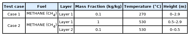
Initial Conditions of the Methane Mass Fraction for the Fire Simulation
The eddy dissipation concept (EDC) model which assumes that the turbulent mixing dominates the combustion was applied rather than the detailed chemical kinetics. The 'Simple Chemistry' was selected, whereby water and carbon dioxide were generated as the fuel underwent a single-step reaction, whereas methane was set as the fuel. The fuel properties in the fire simulation are listed in Table 2.

Fuel Properties used in Fire Simulation
The burner was set to the heat release rate per unit area (HRRPUA) of 1,000k W/m3. Taking into account the air flow through the entrance door right at the onset, the maximum heat release was set to occur 4 s after the onset. The computation time was set to 20 s to ensure the adequate monitoring of the backdraft.
3. Results and Discussion
3.1 Small compartment experiment
In a single experimental setup, a total of ten backdraft experiments were consecutively performed. As shown in Figure 5, backdraft did not occur in the first four experiments owing to the low compartment temperature. Hence, at the end of the fourth experiment, an additional 200 g of wood pieces was supplied. To increase the compartment temperature, it was waited until the wood combustibles actively burn and the fifth to the tenth experiments were performed, where backdraft was observed.
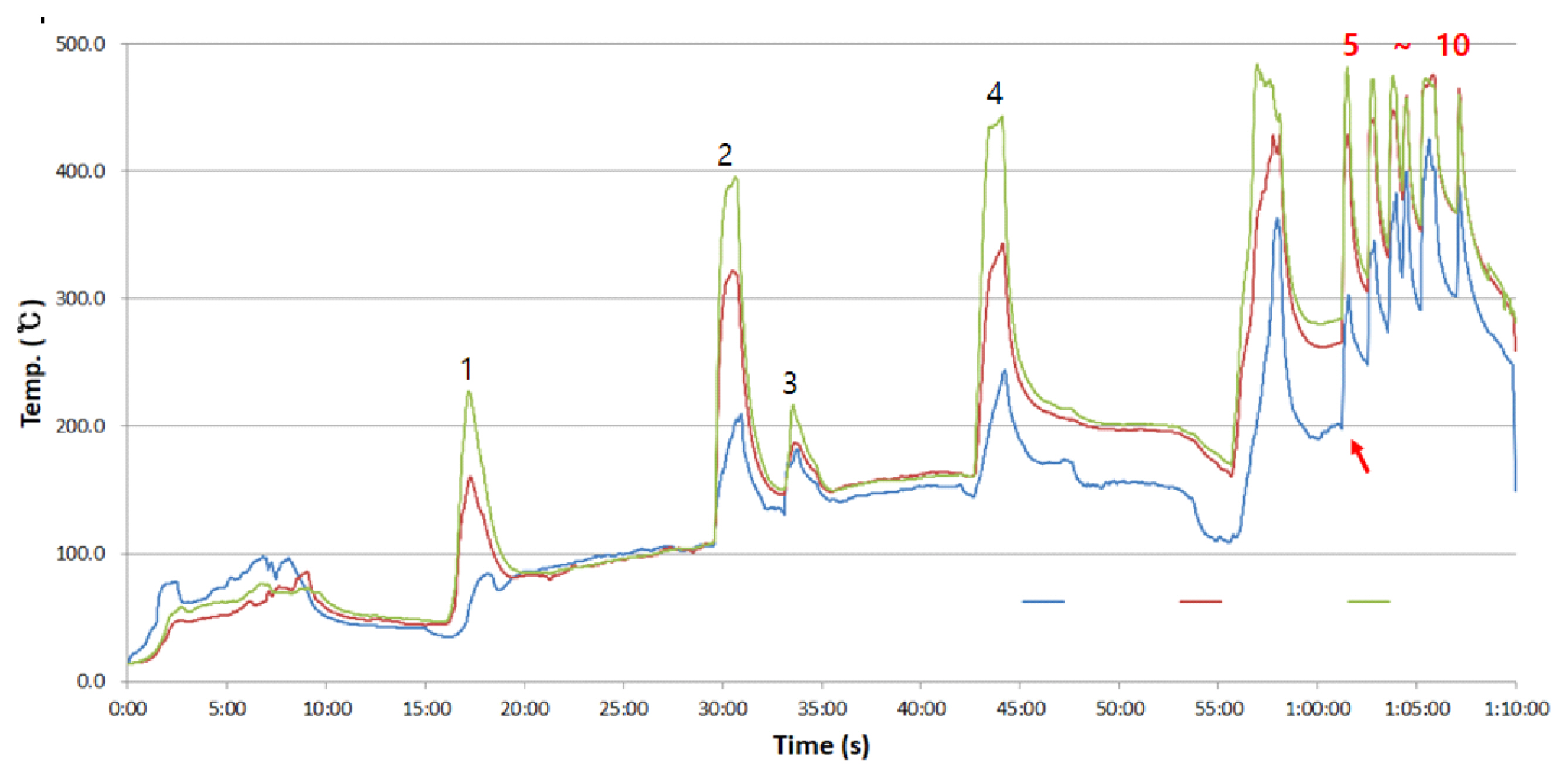
Average temperature history inside the compartment (green: top, red: middle, blue: bottom).
Table 3 summarizes the mean temperature prior to the generation of flame on the wood combustibles following the vent opening. In the first to fourth experiments without backdraft, the mean temperature inside the compartment prior to the flaming fire was low in the range of 59-156 ℃, whereas in the fifth to tenth experiments with backdraft, the mean temperature prior to the flaming fire was higher by 100-200 ℃ in the range of 250-360 ℃. The time taken for the conversion to the flaming fire with the air flowing into the compartment via the vent opening was inconsistent, from as short as 17 s to as long as 2 min.
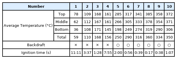
Average Temperature before Backdraft and Ignition Time
The flame propagation inside the compartment was analyzed based on the fifth experiment among the fifth to the tenth experiments with backdraft. At the end of the fourth experiment, combustibles were added to increase the mean temperature up to 409 ℃ at the central upper and lower parts, then all the openings were closed. After 1 min 15 s, the flame inside the compartment was extinguished owing to the lack of oxygen, at which state the vent was opened, whereas the rear vent was opened after 22 s. Backdraft occurred after 2 min of the front vent opening with more active supply of air after opening the rear vent.
For the ignition inside the compartment, the increased air supply after the vent opening and the subsequent opening of the rear vent led to the increased burning of the wood combustibles in smoldering at the lower part on the left of the compartment, as can be seen in Figure 6(b). The flame that was ignited at the lower part spread across the entire wood combustibles, leading to the smoke combustion on the immediate upper part. Next, the flame was generated diagonally at the upper part on the right. The rapid combustion of the unburned gas caused the expansion of the gas on the interior, and the flame was released to the exterior through the vent. Once the smoke inside the compartment had completely burnt out, the combustion proceeded only on the wood combustibles in the common form of fire. The time between ignition and release was within 1 s.

Backdraft caused by opening the front and rear vent of the compartment.
3.2 Fire simulation
Figure 7 shows the mean temperature inside the compartment in the fire experiment and simulation results. The initial combustion led to considerably high temperatures at the center and upper part as well as a slight variation. However, this is presumed to be due to the relatively wide scope of flame propagation in a rapid backdraft in the fire experiment. In the fire experiment, a reduced compartment model was used, but the fire simulation reflected the conditions of an actual fire in a building so that the latter was approximately 6.7 times higher in the simulation scale. However, the reduced compartment was of a middle scale rather than a small scale so that the flame growth and propagation did not vary greatly from the common form of fire. The simulation, likewise, was of an actual scale rather than a reduced scale, and the results were thus anticipated to be useful in field applications and posed no particular challenge in the comparative analysis.
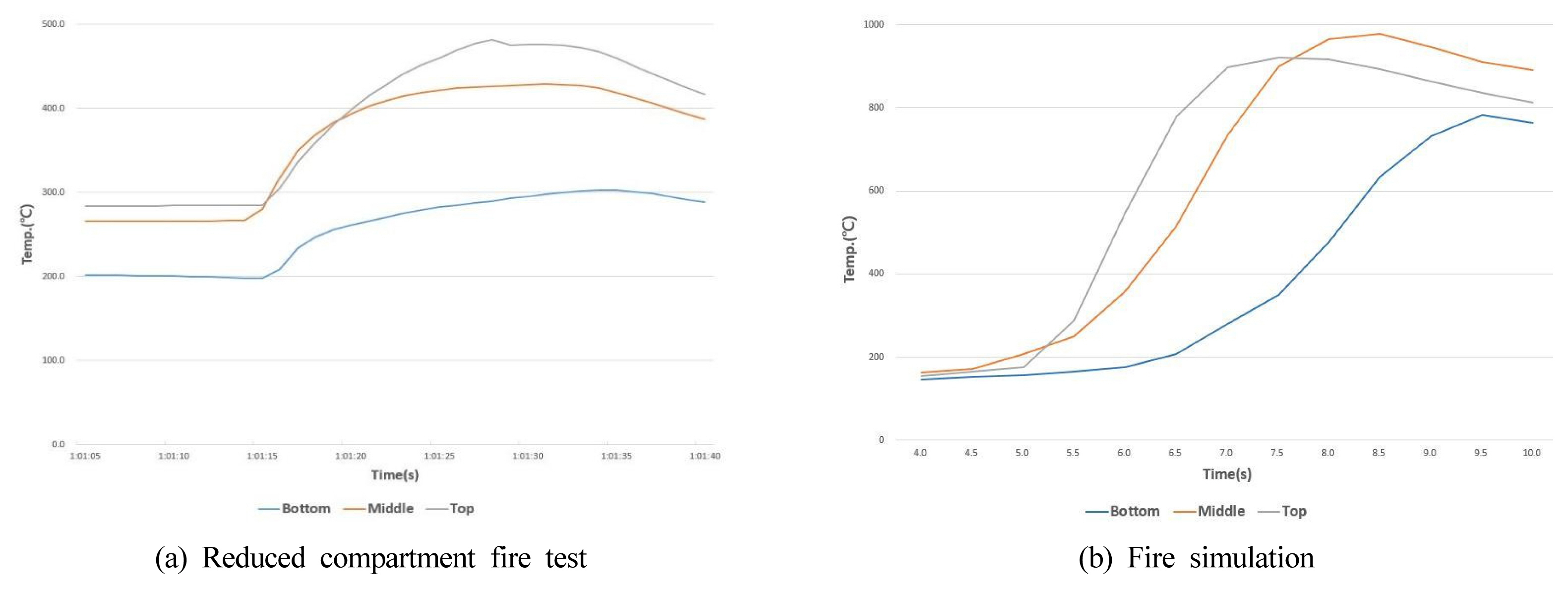
Average temperature history inside the compartment (grey: top, red: middle, blue: bottom).
Figure 8 shows the release of the flame following the ignition. The regions exhibiting the HRRPUV above 200 kW/m3 were highlighted to present the reaction domains. The flame propagation inside the compartment along the area of the flame was analyzed. In Case 1, the ignition of the burner at approximately 4 s led to the ignition of the methane of 0.1 mass fraction at the immediate upper part of the burner. This caused the propagation at the entire upper part on the right, followed by the descent of the flame to the lower part and subsequent powerful release for approximately 1 s through the vent at approximately 6.6 s. In contrast, in Case 2, the ignition of the burner at approximately 4 s did not cause the flame propagation to the upper part. Instead, the spread to the right on the level close to the center inside the compartment led to approximately 1 s release through the vent at approximately 6.1 s. The flame of methane ignition in Case 2 took the form of combustion along the area of the boundary between the two layers. The flame propagation in Case 1 displayed a higher level of similarity to the fire experiment result. Therefore, it was predicted that an actual backdraft would occur as in Case 1, following the formation of a homogeneous mixture on the interior.

Region of which heat release rate is higher than 200kW/m3.
Figure 9 presents the oxygen volume fraction (mol/mol) inside the compartment. In Case 1, the initial level at approximately 0.17 was followed by a sudden fall of O2 -1 (at the upper part on the left) at approximately 5 s after the burner ignition to record 0.00 at 5.4 s; the fall of O2 -2 (at the central upper part) began at 5.4 s to record 0.00 at 5.6 s; the fall of O2 -3 (at the upper part on the right) began at 6.1 s to record 0.00 at 6.4 s. This is, as explained in Figure 6, due to the flame propagation from the interior of the compartment. In Case 2, as the initial condition was set for the compartment to be filled up with methane, the initial oxygen volume fraction was 0.0, whereas the increase in level was first displayed by O2 -2 at approximately 5.5 s, followed by O2 -1 at approximately 5.6, s and O2 -3 at approximately 6.6 s. This is due to the influence of the buoyancy created by the flame coming in contact with the oxygen flowing in from the exterior and to the rising air current with the external oxygen at the center of the compartment.
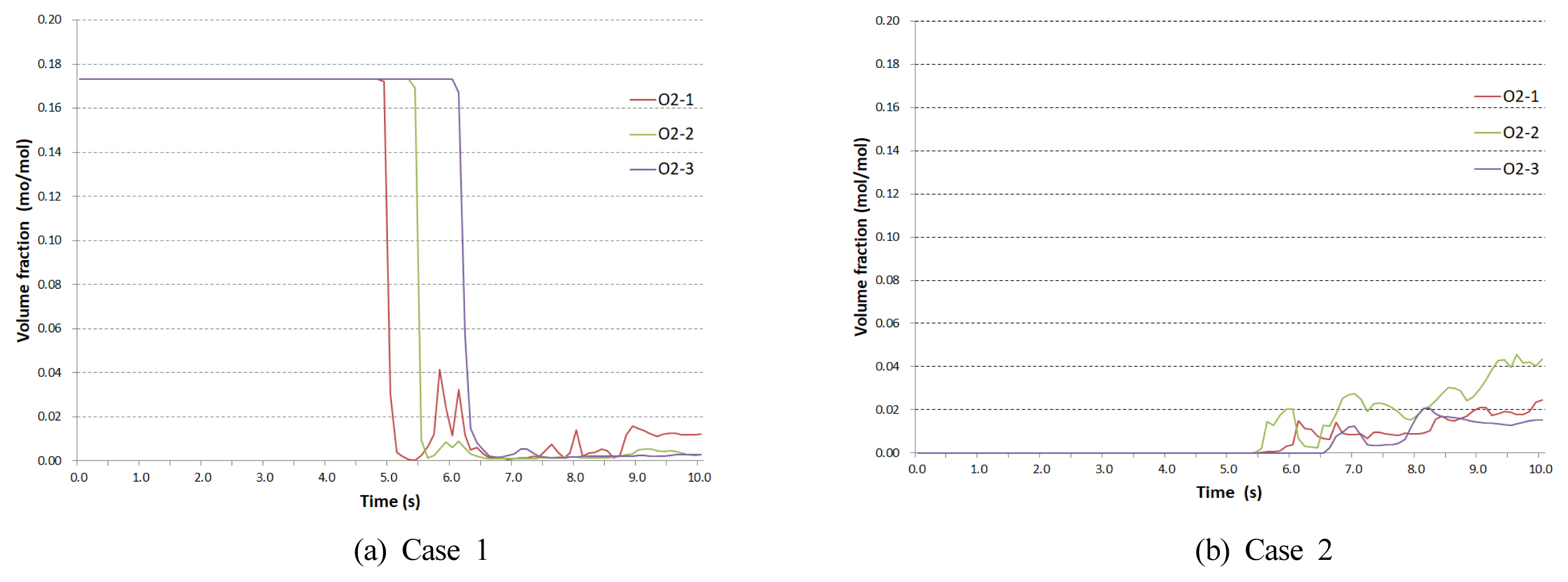
Oxygen volume fraction inside the compartment.
Figure 10 presents the distribution of the oxygen volume fraction at the central cross-section (y = 1.5 m) of the compartment. In Case 1, the combustion area reaches O2 -1 at 5.01 s, passes the midpoint at 5.55, s and passes O2 -3 at 6.03 s. This reflects the sequential fall in oxygen concentration from O2 -1 to O2 -2 to O2 -3 in Figure 9. A pattern of release of the internal mixture to the exterior was observed during the process of flame propagation, and the release of the flame to the exterior was followed by the ignition of the released flammable mixture towards combustion. In Case 2, the rising air current due to the buoyancy at the center of the compartment was observed at approximately 5.01 s. At 5.55 s, a partial mixing between O2 -1 and O2 -2 occurred, and at approximately 6.51 s, the combustion led to the expansion in the direction of O2 -3 to cause the release of the flame to the exterior.

Distribution of the oxygen volume fraction.
3.3 Backdraft mechanism derived from the experiment and simulation
In the reduced compartment fire test, a backdraft occurred as the air supplied via the vent opening caused the flaming ignition of the wood combustibles in a smoldering state. It was followed by the combustion of the smoke exhaust on the upper part of the compartment through the flame, after which the flame was propagated downwards to generate the passage through the vent. This coincided with the flame propagation pattern in the fire simulation, where the mass fraction of total methane in the compartment was set to 0.1. Figure 11 summarizes the backdraft mechanism derived in this study. Through the reduced compartment fire test and the fire simulation, the phenomenon of backdraft was simulated and analyzed. The results confirmed the generation of a flammable mixture throughout the compartment, leading to the propagation of the flame to the upper part of the compartment. The backdraft mechanism elucidated in this study can be summarized as follows:
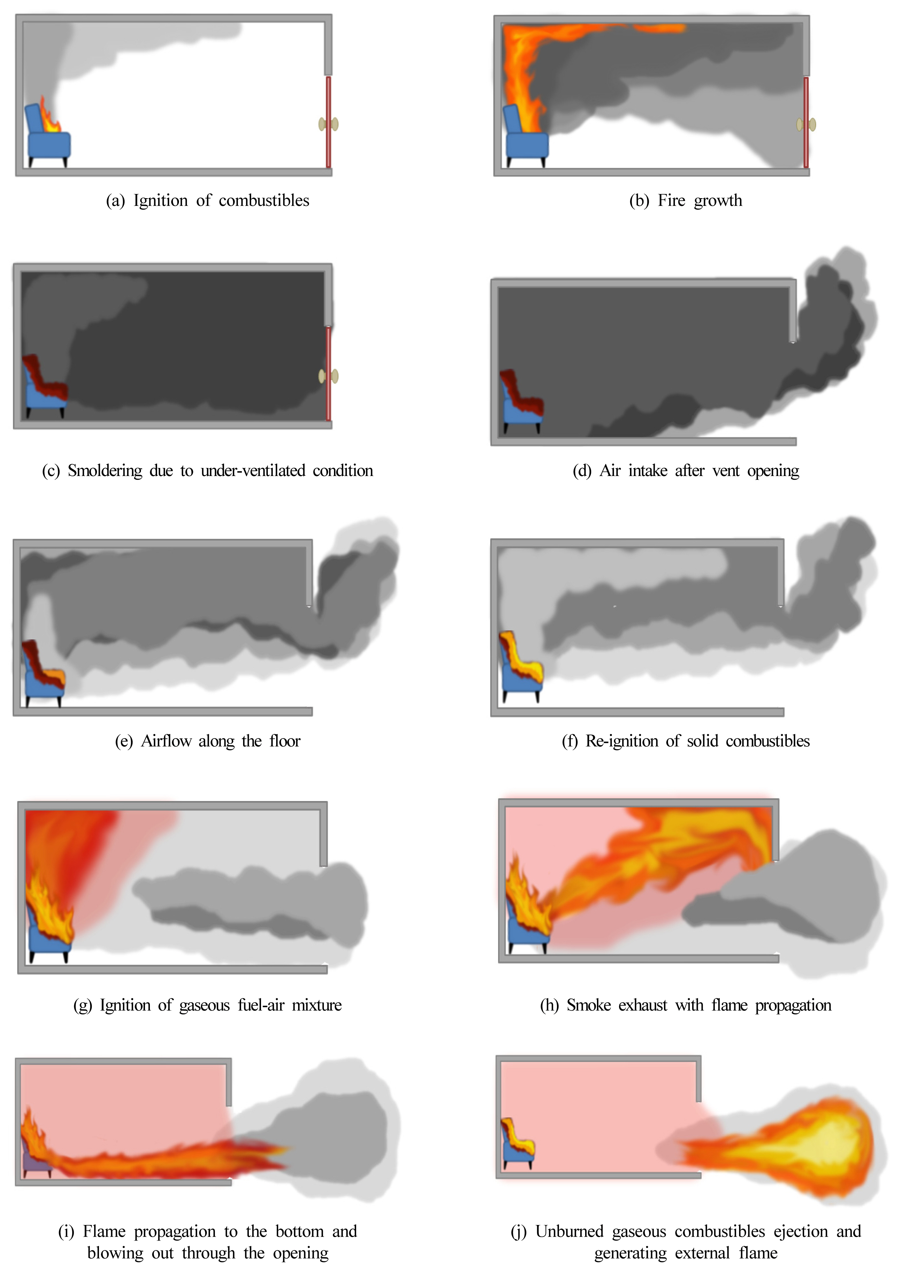
Backdraft mechanism.
① Fire is generated in the sealed compartment, and the limited amount of air leads to a state of oxygen deficiency.
② The lack of oxygen causes smoldering combustion, which leads to the accumulation of heat and flammable gas in the compartment.
③ Air flows in via the vent opening, leading to the mixing of flammable gas and air.
④ A certain part of air mixes with the flammable gas on the upper part through the upstream air flow generated by the smoldering heat.
⑤ Continuous air flow changes the smoldering fire into the flaming fire.
⑥ The flame causes the ignition of the flammable gas mixture on the upper part.
⑦ With the rise in internal pressure following the combustion of the gas mixture, the smoke is released through the vent.
⑧ The flame inside the compartment is released through the opening and propagates outside of the compartment.
⑨ The released smoke mixes with the air on the exterior for the ignition caused by the released flame, which creates the flame on the exterior.
In the reduced compartment fire test in this study, various phenomena from lack of backdraft to the release of smoke only or release of powerful flame were observed based on varying conditions including the indoor temperature, volume of air flow, amount of combustibles, and concentration of smoke. Additional studies should be conducted regarding specific conditions of the generation of various forms of backdraft.
4. Conclusion
In this study, a backdraft was simulated in a reduced compartment fire test using solid combustibles. The phenomena inside the compartment upon the backdraft were analyzed through a fire simulation. The results of this study are summarized as follows:
1. In the reduced compartment fire test, the burning of an adequate amount of wood pieces caused high temperatures, and a backdraft was observed. Upon the backdraft, the smoldering fire of the solid fuel turned into the flaming fire, leading to the ignition of the flammable gas-air mixture. After the ignition, the flame was propagated from the location of the solid fuel towards the exterior of the compartment.
2. The fire simulation showed the flame propagation behavior that resembled the pattern in the experiment where the flammable gas and air were in a homogeneous mixture inside the compartment. After the ignition using combustibles, the flame was propagated first to the upper part of the combustibles, then sequentially to the center and exterior of the compartment.
3. The backdraft mechanism thus involves the following processes: 1) The smoldering fire of solid combustibles meeting the air through the vent to generate the flaming fire; 2) The flaming fire causing the ignition of the mixture of flammable gas and air on the interior; 3) The propagation of the flame to the upper part of the combustibles and then towards the vent; 4) The rise in internal pressure causing the smoke exhaust to be released to the exterior; 5) The flame on the exterior causing the ignition of the mixture of smoke exhaust and air.
Notes
Author Contributions
Conceptualization, methodology, investigation, writing—original draft preparation, J. An; investigation, writing—review and editing, supervision, T. Kim. All authors have read and agreed to the published version of the manuscript.
Conflict of Interest
The authors declare no conflict of interest.