
1. Introduction
In South Korea, more than 40,000 fires occur annually. According to the fire statistics provided by the National Fire Data System[1], a total of 36,267 fires occurred in 2021. As for the causes of the fires, carelessness accounted for the largest proportion (46.5%) followed by electrical factors (26.1%; 9,472 cases). A detailed analysis of the fires caused by electrical factors revealed that unidentified short circuits accounted for the largest proportion (29.3%; 2,780 cases) of the causes, followed by short circuits due to insulation degradation (21.3%; 2,021 cases), short circuits due to tracking (12.40%; 1,201 cases), short circuits due to poor contact (10.7%; 1,021 cases), overload/overcurrent (7.9%; 757 cases), and short circuits due to compression damage (4.6%; 437 cases). In addition, when the number of fires caused by ignition devices in 2021 was analyzed, it was found that a total of 15,881 fires occurred in equipment and devices. Among them, fires that occurred in wiring and wiring devices accounted for 13.3% (2,113 cases) of the total. As the proportion of fires caused by electrical factors and wiring increases each year, continuous research on insulated wires and wiring is required. Hyeong-ju Park[2] and Si-kuk Kim[3] have conducted studies on short circuits due to insulation degradation, which account for the highest proportion of the fires caused by electrical factors. Studies on poor contact, tracking, and overcurrent have been conducted by Chung-seok Choi[4], Seung-wook Ji[5], and Jeong-jin Lee[6]. Short circuits due to compression damage, however, have not been extensively researched in relation to their prevention and fire investigation, although more than 500 cases are reported annually. In addition, research on deriving the detailed causes of fires due to electrical factors has been insufficient because previous studies have primarily focused on establishing safety measures following the occurrence of electrical defects that result in fires. Thus far, no study has investigated the thermal properties of electric wires subjected to compression damage. As for such compression damage to wiring, there are cases in which wires are twisted due to the wall structure and the shape of the structure. In addition, wires are generally installed at the bottom after passing through structures during the wiring and installation of electronic devices in a house. In such cases, the wires are likely to be damaged by moving objects or residents stepping on them. There are also many cases in houses, general offices, and workshops, where wire protection tubes that protect the wiring of electric devices or equipment are not installed, resulting in wire compression caused by heavy objects, such as bookshelves and desks. An increase in compression pressure on insulated wires damages the wires, which increases the risk of fire due to the accumulation of heat. Insulated wires are most significantly affected by the use of electricity and are mainly used indoors. As a voltage of 220 V that can cause death in the event of an electric shock is generally used in indoor wiring, special maintenance and inspection are required. However, owing to the nature of wiring and electronic devices used in houses, they are typically used continuously without being replaced or repaired until any particular problem occurs after installation.
Therefore, this study aimed to analyze the risk of electric fires caused by compression damage. A KIV insulated wire (450/750 V general-purpose flexible single-core vinyl insulated wire, code symbol: 60227 KS IEC 02) that is typically used in household electrical installations, was utilized as an experimental sample. The breakage of the insulated wire, caused by compression damage, was measured by quantitatively identifying damage to the wire, using a compression testing machine and stand. In addition, changes in the thermal properties due to wire breakage were measured by applying an allowable current of 30 A (100%) and stepwise overcurrent values of 45 A (150%) and 60 A (200%) to the insulated wires damaged and cut by compression.
2. Experimental Sample and Scope
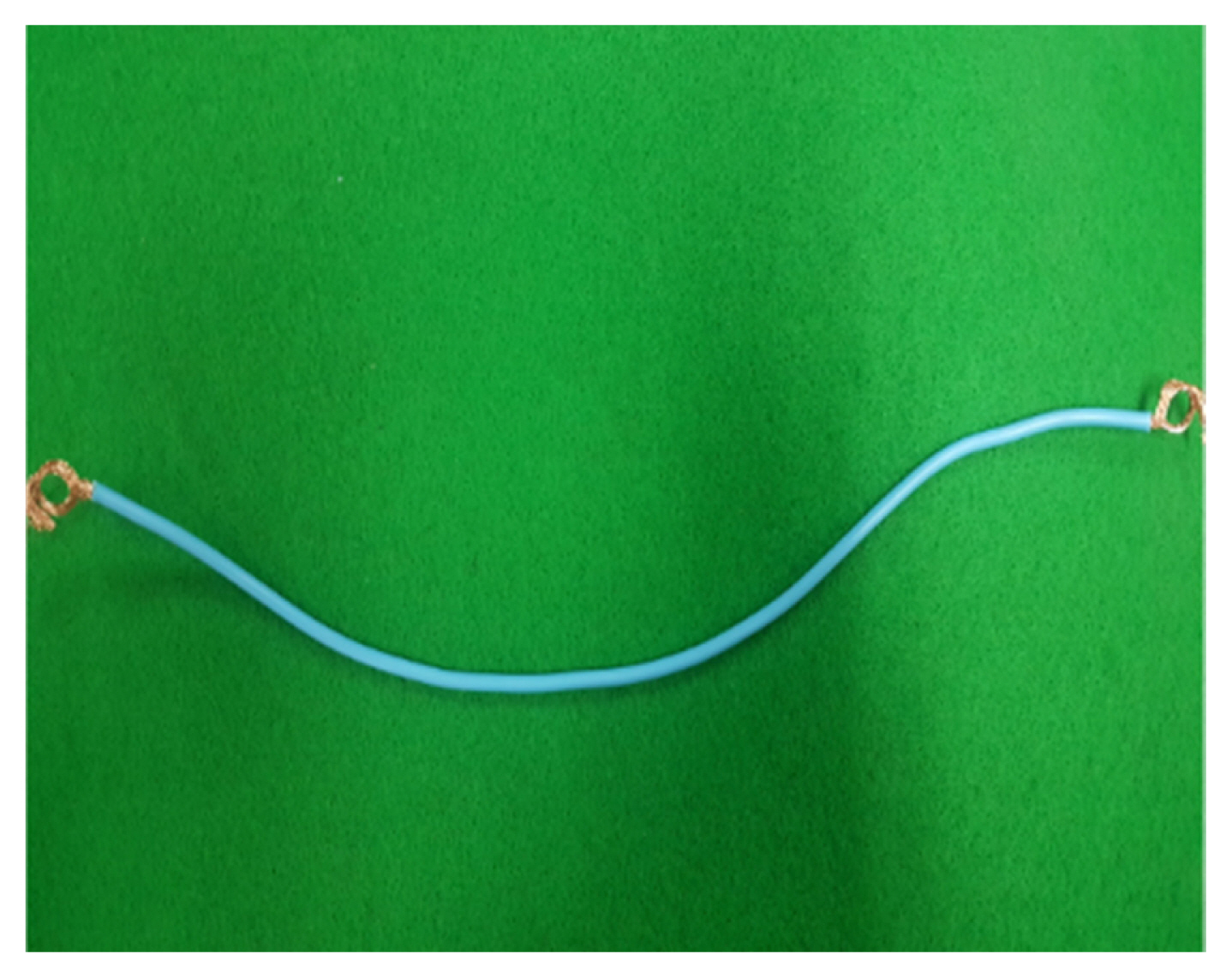
The experimental sample considered in this study was a KIV insulated wire (450/750 V general-purpose flexible single-core vinyl insulated wire, code symbol: 60227 KS IEC 02), which is typically used in everyday life, as shown in Figure 1. The sample was cut to a length of 500 mm before use. Table 1 lists the specifications of the electric wire. The electric wire had a sectional area of 2.5 mm2 and 44 wire strands (44 C). Its maximum allowable temperature was 70 °C. In addition, all tests were conducted at a temperature of 20 ± 3 °C and humidity of 45 ± 5%. A compression testing machine and stand were used to measure the applied pressure and wire breakage due to compression for different cross-sectional area of the insulated wire. An additional experiment was performed to analyze the thermal properties of the insulated wire according to wire breakage and observe the process through which the wire sheath melted as a result of compression damage.
3. Experiment
3.1 Measurement of applied pressure and wire breakage for each cross-sectional area of the insulated wire subjected to compression damage
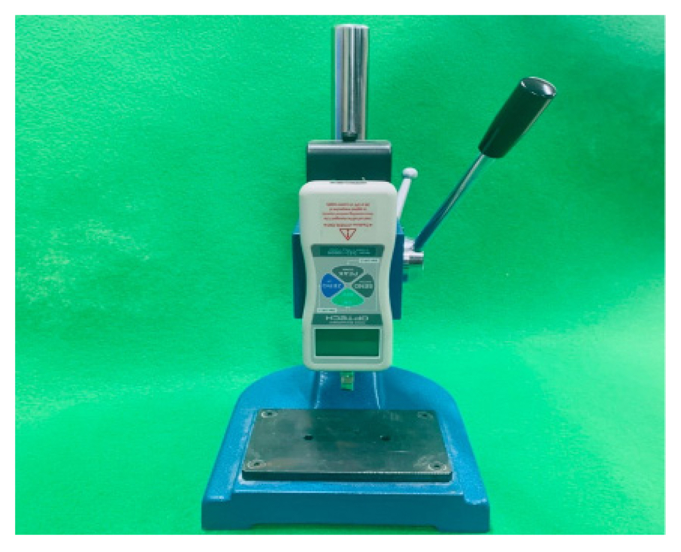
Figure 2 shows the compression testing machine (Optech, DS2-1000N, Japan) and stand (Optech, SV-1K, Japan) used to measure the pressure on the insulated wire by subjecting it to compression. Figure 3(a) shows the metal triangular jig used to apply compression to each cross-sectional area of the insulated wire. The pressure and wire breakage measurement experiment was performed 15 times, and the average values were calculated. Cases in which 25, 50, 75, and 95% of the cross-sectional area of the insulated wire, including the insulator, were cut using the triangular jig were considered, as shown in Figure 3(b), to derive the quantitative value of the load pressure using the compression testing machine. Measurements were recorded until the insulated wire was cut by the triangular jig.
3.2 Experiment on thermal properties according to wire breakage by compression damage
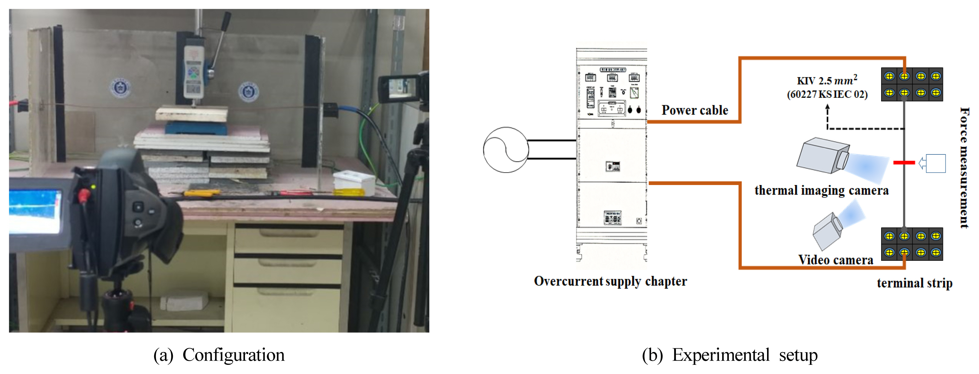
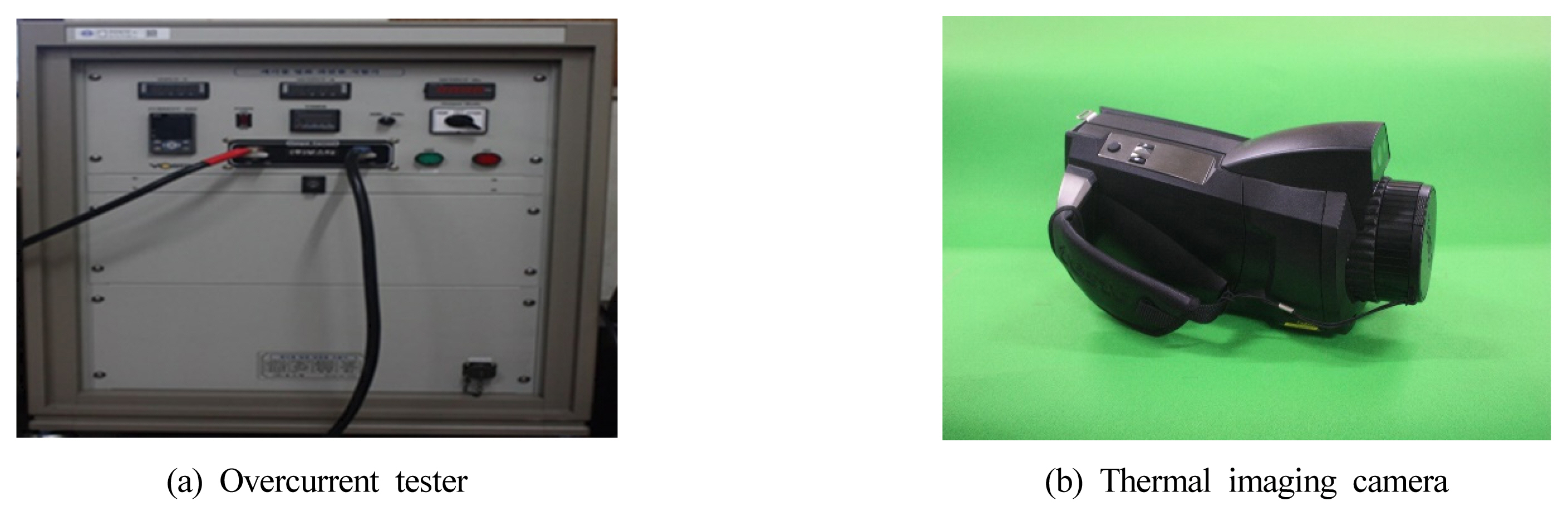
This experiment was performed to identify the thermal properties according to the wire breakage. Figures 4(a) and 4(b) show the configuration of the experiment. The experiment was performed 15 times, and the average values were calculated. The duration of the experiment was set to 600 s for the safety of the experiment and experimental setup. This experiment was performed to investigate the thermal properties of the insulated wire subjected to compression pressure, as in the previous experiment in Section 3.1. The breakage of the insulated wire was set to 25, 50, 75, and 95% in the experiment. An allowable current of 30 A was applied for the KIV insulated wire; in addition, currents that were 1.5 and 2 times the allowable current, i.e., 45 A and 60 A, were applied. These reflected the conditions of performing the experiment in an open place and considering the allowable current value of a multi-core 2.5 mm2 cable installed using method described in the electrical wiring code. Considering that the operating time of the circuit breaker for 30 A wiring usually used in apartments is 60 min when the current is 1.6 times (48 A) the rated current, a current reduced by 3 A, i.e., a current of 45 A, was applied. In addition, a current of 60 A was applied considering that the operating time is 2 min at 60 A (twice the rated current). Figure 5(a) shows the overcurrent tester (AFC-1010, Vosta Co., Korea) used to apply current to the insulated wire. The thermal properties were determined by measuring the temperature of the insulated wire according to the wire breakage using a thermal image camera (Testo 885, Testo Co., Germany), as shown in Figure 5(b).
4. Experimental Results and Discussion
4.1 Results of the applied pressure and wire breakage measurement experiment for each cross-sectional area of the insulated wire due to compression damage
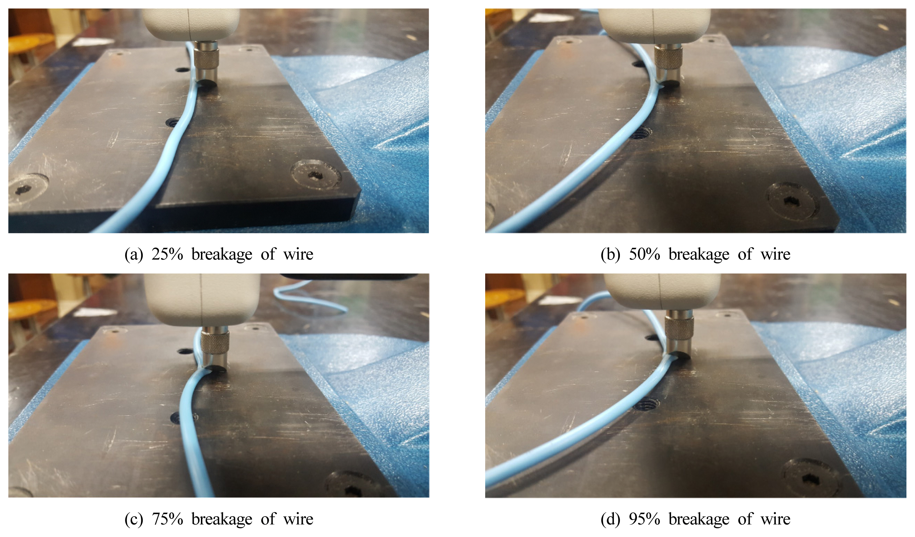
The wire breakage was measured for each cross-sectional area of the insulated wire subjected to compression by the triangular jig. Table 2 shows the quantitative pressure values derived using the compression testing machine for cases in which 25, 50, 75, and 95% of the cross-sectional area of the insulated wire, including the insulator, were damaged. When a load of 50 ± 3 kgf was applied, 25% of the cross-sectional area was damaged, and 11 ± 2 copper strands were cut. When a load of 70 ± 3 kgf was applied, 50% of the cross-sectional area was damaged, and 22 ± 2 copper strands were cut. When a load of 90 ± 3 kgf was applied, 75% of the cross-sectional area was damaged, and 33 ± 2 copper strands were cut. When a load of 110 ± 3 kgf was applied, 95% of the cross-sectional area was damaged, and 40 ± 2 copper strands were cut. The compressive strength required to cut the entire cross-sectional area of the wire was found to be 130 kgf. Figure 6 shows the photographs of the experiment performed to measure the compressive strength and wire breakage when 25, 50, 75, and 95% of the insulated wire was damaged. A compressive load of approximately 50 ± 3 kgf was required to cut 25% of the cross-sectional area (2.5 mm2) of the insulated wire. This is the same load as that of a commonly used bookshelf filled with general office supplies. If the insulated wire is compressed and pinched by such a structure, it is judged that the wire will be easily damaged. Compressive loads of 70 to 90 kgf were required to cut 50 and 75% of the insulated wire, respectively. This is the approximately the same weight as that of an adult male. If the insulated wire is exposed to continuous stepping, pinching via bookshelves, or compression by the loads of products, such as large electronic devices, refrigerators, and air conditioners, more than 50% of it can be damaged and cut, thereby significantly increasing the risk of fire. The experiment results were obtained by applying compression to new products that were not used before and measuring the wire breakage. Considering that the insulated wires in buildings, such as general houses and offices, are used continuously, as long as no product defect occurs, it is judged that damage due to aging and insulation degradation can also occur in the insulated wires. According to a previous study[7], when insulation degradation due to the aging of insulated wires persisted, the degree of hardening increased, and the insulator was easily damaged by a minor impact. This indicates that aged insulated wires can be more easily damaged by compression. In addition, it is highly likely that the insulated wire can be damaged and cut under a load that is lower than the quantitative data presented in this paper because of aging.
4.2 Results of the experiment on thermal properties according to wire breakage by compression damage
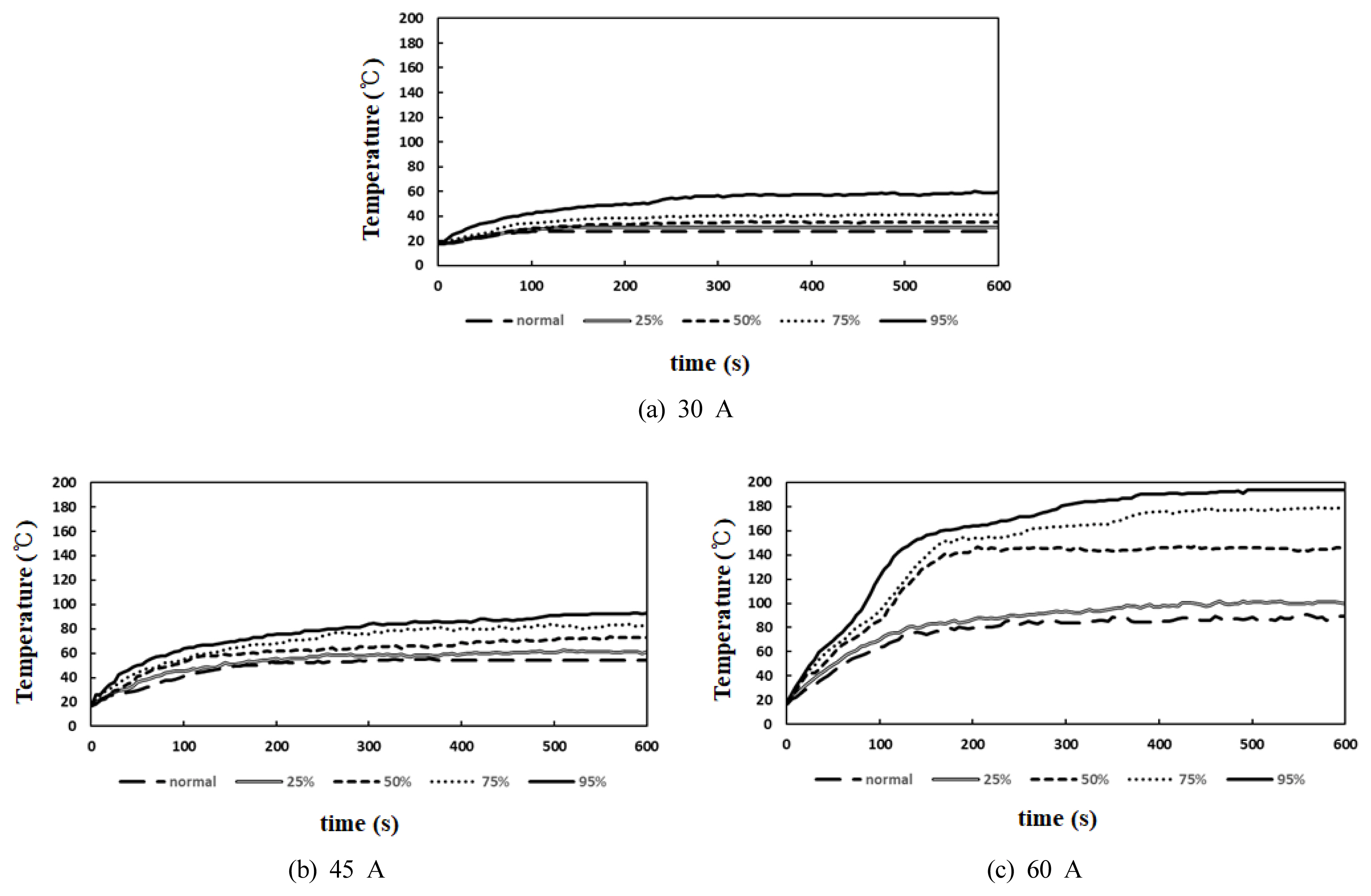
This experiment was performed to examine changes in the thermal properties when the insulated wire is damaged and cut by compression. Currents of 30, 45, and 60 A were applied to the insulated wire exposed to 25, 50, 75, and 95% damage for 600 s, and the thermal properties and maximum temperature of the wire were analyzed. Table 3 lists the thermal properties according to the wire breakage caused by compression damage. When a current of 30 A was applied, the maximum temperature of the insulated wire was measured to be 28 °C for a normal sample, 31 °C for 25% damage, 35.8 °C for 50% damage, 41.6 °C for 75% damage, and 59.9 °C for 95% damage. The maximum temperature of the sample with 95% damage was approximately 31.9 °C higher than that of the normal sample. When a current of 45 A was applied, the maximum temperature of the insulated wire was measured to be 55.7 °C for a normal sample, 62.2 °C for 25% damage, 73.5 °C for 50% damage, 83.7 °C for 75% damage, and 93 °C for 95% damage. The maximum temperature of the sample with 95% damage was approximately 37.3 °C higher than that of the normal sample. When a current of 60 A was applied, the maximum temperature of the insulated wire was measured to be 90.8 °C for a normal sample, 102 °C for 25% damage, 147.9 °C for 50% damage, 179 °C for 75% damage, and 193.8 °C for 95% damage. The maximum temperature of a sample with 95% damage was approximately 103 °C higher than that of the normal sample.
Figure 7 shows the changes in temperature with applied current according to the wire breakage by compression damage. Figure 7(a) shows the temperature of the insulated wire temperature when the supplied current is 30 A. It can be seen that the temperature of the insulated wire increases as the degree of compression damage increases. When a current of 45 A was applied, the temperature almost doubled compared to when a current of 30 A was applied; it increased by 31.2 °C for 25% damage, 37.7 °C for 50% damage, 42.1 °C for 75% damage, and 33.1 °C for 95% damage. When a current of 60 A was applied, the thermal properties could clearly be determined. Compared to 30 A, the temperature increased by 71 °C for 25% damage, 112.1 °C for 50% damage, 137.4 °C for 75% damage, and 133.9 °C for 95%%. When the compression damage was 50% at 60 A, the copper strands were exposed as the sheath melted by the end of the experiment and the temperature dramatically increased due to this exposure of the copper strands. Sheath melting occurred at approximately 183 s for 50% damage, 155 s for 75% damage, and 120 s for 95% damage. When the insulated wire temperature for 50, 75, and 95% damage at 60 A was examined, it was found that the temperature rapidly increased after the sheath melted. By measuring the thermal accumulation temperature of copper strands using a thermal imaging camera after the exposure of the strands, it was confirmed that the temperature remained constant after a certain period of time.
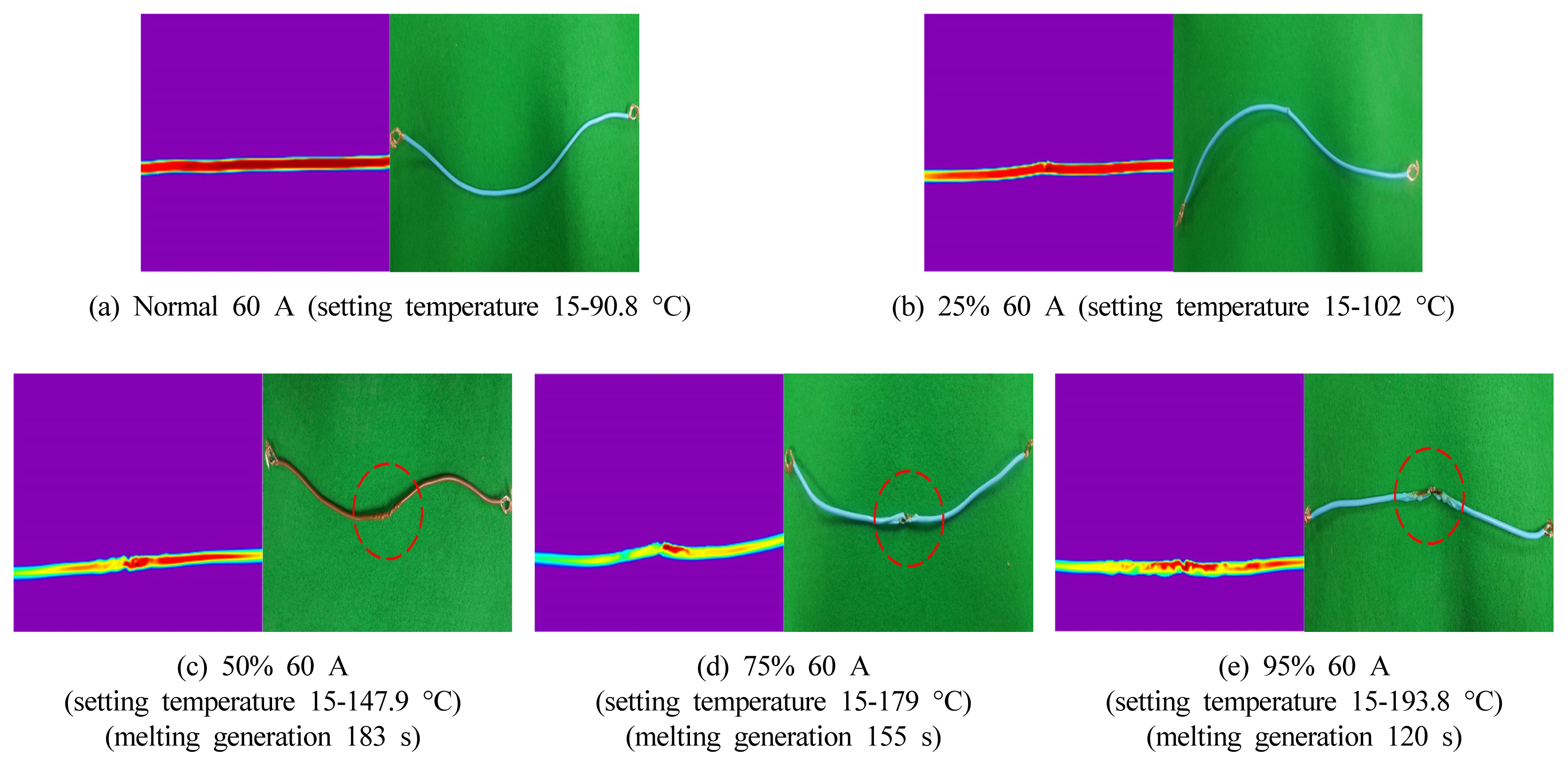
Figure 8 shows the temperature characteristics captured using the thermal imaging camera. Figures 8(a) and 8(b) indicate that the temperature distribution was even over the entire area of the insulated wire in response to the setting temperature. However, when the degree of damage increased to 50% or higher as shown in Figures 8(c), 8(d), and 8(e), the heat accumulated in the damaged local area. As this phenomenon continued, sheath melting occurred relatively early, within 200 s after the start of the experiment, and resulted in carbonization. The reason that the thermal energy increase with an increase in damage can be explained by Joule’s law (H [J] = 0.24I2RT). Here, H is the amount of heat generated [cal], I is the current [A], R is the resistance [Ω], and t is the time [s]. When the insulated wire is damaged, the area of the conductor that moves the current decreases, thereby increasing its resistance. In addition, the contact resistance increases at the cut local area, while the indirect contact and separation of copper strands are repeated, thereby increasing thermal properties. This phenomenon increases the risk of fire. The temperature difference between the supplied currents of 30 A and 45 A may not be considered significant because the experiment was performed within a relatively short period of time (less than 10 min). However, in a case where insulated wires are installed in buildings, they are used over a long period. As a result, a temperature difference of 20 to 30 °C is expected to sufficiently increase the possibility of a fire owing to the heating phenomenon caused by long-term heat accumulation.
5. Conclusion
In this study, the pressure applied to each cross-sectional area of the insulated wire due to compression and the thermal properties of the wire according to the compression damage were analyzed. The following conclusions were drawn.
When 25% of the cross-sectional area of the insulated wire was damaged by compression, the applied load was found to be 50 kgf. A load of 70 kgf was required for 50% damage, 90 kgf for 75% damage, and 110 kgf for 95% damage. The compressive strength required to cut the entire cross-sectional area of the wire was found to be 130 kgf.
It was confirmed that the maximum temperature of the wire exceeds the allowable temperature for the wire sheath (approximately 75 °C) when the wire is damaged by heavy and sharp objects. The temperature also increases more rapidly in a damaged wire than in a wire without damage.
In particular, when an allowable current of 30 A was applied, the maximum temperature increased to 59.9 °C under a load of 110 kgf; other experimental studies have shown similar maximum temperatures of approximately 40 °C. When an overcurrent of 60 A was applied, the temperature increased to 147.9, 179, and 193.8 °C under loads of 70, 90, and 110 kgf, respectively, indicating that the possibility of a fire occurring, as a result of local breakage, is high when electric wires used in daily life are pressed over a long period.
In this study, the fire risk for electric wires was determined considering the changes in the thermal properties caused by compression damage. In everyday life, however, people are directly exposed to electrical accidents and fire risks, because electric wires of home appliances and electric devices are frequently used while they are under compression. Therefore, it is necessary to keep electric wires from being pressed by objects or against the floor by using protective frames to prevent fires caused by compression damage. In places where a large number of electric wires are used, it is necessary to take precautionary measures, such as arranging cluttered wires using wire harnesses and cable ties.