• Home
  • Sitemap
  • Contact us
Int J Fire Sci Eng Search

CLOSE


Int J Fire Sci Eng > Volume 36(3); 2022 > Article
Ha and Oh: Comparative Study on Theoretical and Numerical Calculations of Mass Flow Rate through Opening of Compartment

Abstract

In this study, stratified, well-mixed, and simplified theoretical model equations and Fire Dynamics Simulator (FDS) were used to calculate the mass inflow, outflow and neutral height to determine the usefulness of previously proposed simple formulas for the calculation of the mas flow rate through openings of compartments in case of fire. The mass flow rate through the opening was evaluated for two conditions, i.e., a fire inside the compartment and no fire, with a high-temperature homogeneous mixture filled inside the compartment. The height of the neutral plane calculated using the theory and FDS under the condition of fire inside the compartment well obeyed the trend of the experiment. In particular, the FDS results for the neutral plane height and inlet air mass flow well agreed with the experiment. However, for the inlet air mass flow rate, the theoretically obtained stratified and well-mixed model equations overestimated the mass flow variation trend according to the increase in opening width. The results of the stratified model equation were the most consistent with the FDS calculation results regardless of temperature, under the condition of a uniform mixture inside the compartment. Regarding the inlet air flow rate, the difference between the theoretical equation result and FDS result was not small. In contrast, for the effluent air flow rate, the results of the simplified formula were the most consistent with the FDS results.

1. Introduction

Compartment refers to any limited space that controls the maximum air supply and thermal environment of fire[1]. Fires that can occur in these compartments are very important to understand fires because they exhibit various characteristics of a fire that occurs inside a building[2]. One of the most important factors that determine the nature of a fire in a compartment is the amount of air supplied to the fire inside the compartment. This amount of air has a very large difference depending on whether there is an opening or not. In the case of a closed compartment without an opening, the amount of air inside the compartment has a large effect on the nature of the fire. In addition, in the case of backdraft, which is an explosive fire, as well as a normal fire caused by solid and liquid combustibles inside a compartment with an opening, it is largely affected by the amount of introduced air[3-5]. In particular, in the case of backdraft, it has fire characteristics of both closed compartment and compartment with an opening and, in terms of explosion strength, it is strongly related to the amount of air flowing through the opening. The rate of air flowing in through the opening is also closely related to the flow rate of gas discharged from the compartment to the outside. Therefore, in an analysis of the inflow air flow rate, the flow rate of the outgoing gas is often simultaneously considered.
To understand the characteristics of a compartment fire, numerous studies have been carried out on calculation of the mass flow into and out of the compartment. Among them, many are experimental studies[6-10]. Recently, theoretical studies[11-13] and computational analysis studies[14-17] on mass flow calculation have also been carried out. However, most of these studies have been mainly focused on the conditions under which a fire occurred inside the compartment. In the case of backdraft, it is necessary to review the mass flow through the opening under these conditions as it occurs when a fire occurs inside the compartment, and the combustion products are filled in an almost uniform state after being extinguished.
Steckler et al.[9,10] derived the mass flow theoretically using Bernoulli’s equation and the principle of simple hydrostatic pressure according to temperature distribution through experiments and theories on compartment fires. By comparing the inflow measured in the experiment with the amount calculated by the theoretical formula, the mass flow into the compartment could be explained theoretically. Karlsson and Quintiere[12] theoretically studied the prediction of mass flow through openings and proposed useful equations for the temperature and height of the smoke layer inside the compartment. The equations for mass flow in and out of the compartment were derived using the pressure difference inside and outside the compartment for calculations in the case of a fire that normally occurs. According to the layer distribution of the fire phenomenon in the compartment, a mass flow calculation formula for the case where the smoke is stratified (stratified case) and case where the smoke is completely mixed (well-mixed case) was proposed.
Wang et al.[15,16] reviewed the predictive performance of the inlet air flow calculated by Fire Dynamics Simulator (FDS) through comparison with the existing compartment fire test. In this study, the rate of mass flow into the compartment was reviewed when a heating value of 62.9 kW was used under the conditions of three openings with the same height and different widths of the compartment opening. Considering the temperature of the lower part of the compartment, height of the smoke layer, and height of the neutral plane, an accuracy of 96% was obtained for the inflow mass flow; however, satisfactory results were not obtained for other variables.
Because the theoretical mass flow calculation method is very simple, if the reliability of the arithmetic calculation method is high, it can be used to understand the compartment fire and backdraft behavior and prevent fire. However, there was a limitation as the theoretical studies on the mass flow calculation method could not be reviewed under the condition of absence of fire in the compartment.
Therefore, in this study, the results obtained through the existing theoretical formulas and computational analysis for the calculation of the airflow inflow through the opening and mass flow out of the compartment under the conditions that there is a fire inside the compartment and the compartment is filled with a high-temperature homogeneous mixer were reviewed, along with the usefulness of the existing theoretical formulas.

2. Estimation of Theoretical Inflow and Outflow

The theoretical mass flow calculation equation reviewed in this study is the equation[12] proposed by Karlsson and Quintiere. The equations for the two cases of smoke stratification and complete mixing in the compartment and equations for the inlet air flow rate proposed by simplifying these equations were also used. In each of these cases, C_d of 0.7, suggested by Karlsson and Quintiere, was used, while the remaining variables were adpted from the other literatures[9,10].

2.1 Stratified case

The stratified case refers to a state in which a smoke layer is conspicuously formed inside the compartment due to the generation of smoke due to a fire. In the middle of the compartment opening, there is a neutral plane where the pressure difference between the outside and inside is 0.
Based on the neutral plane, a high-temperature smoke (assuming a gas phase) flows out to the upper part of the opening in the compartment, while outside air (Air) flows into the lower part of the opening. At this time, the outflow mass flow rate (gas) and inflow mass flow rate (air) through the opening can be calculated by[12].
(1)
m˙gas=23CdWρgas2(ρair-ρgas)gρgas(H0-HN)3/2,
(2)
m˙air=23CdWρair2(ρair-ρgas)gρair(HN-HD)1/2(HN+12HD),
where Cd is the flow coefficient, W is the width of the opening, ρ is the density, H0 is the total height of the opening, HN is the height from the bottom of the opening to the neutral plane, and HD is the height from the bottom of the opening to the smoke layer. The height of the neutral plane can be obtained through iterative calculations under the assumption that the mass outflow and inflow are same.

2.2 Well-mixed case

Unlike the stratified stage, the stage in which smoke and air are completely mixed inside the compartment implies that the fire is fully developed and that the entire interior of the compartment is filled with smoke. Even at this stage, it can be calculated by dividing the mass outflow and inflow based on the neutral plane in the middle of the compartment. At this time, the outflow mass flow rate (gas) is calculated in the same manner, using Eq. (1), while the inflow mass flow (air) is calculated by
(3)
m˙air=23CdWρair2(ρair-ρgas)gρair(HN)3/2,
where the height of the neutral plane is determined by the following equation, assuming that the mass outflow and inflow are same:
(4)
HN=H01+(ρair/ρgas)1/3.

2.3 Simplified air mass flow calculation formula

Karlsson and Quintiere used the density factor (DF) defined below in the formula for calculation of the mass flow rate of the inlet air for the case of complete mixing, and a simpler formula for calculation of the inlet air mass flow was proposed[12]:
(5)
DF=(ρair-ρgas)/ρair[1+(ρgas/ρgas)1/3]3.
In this study, a value of 0.214, the maximum value suggested as a DF in the literature, was used. The temperature inside the compartment was 800 K, while the temperature outside the compartment was 293 K. As a result, the simplified expression is[12].
(6)
m˙air=0.5AH0.
Eq. (6) can be used for calculation only through the height (H0) and area (A) of the opening. It is used to confirm the approximate mass flow in a simple calculation of an actual fire.

3. Numerical Methods

3.1 Governing equations

For a numerical calculation, FDS v6.3.2[18,19] developed by NIST, mainly used for fire modeling, was employed. FDS uses a low-Mach-number approximation as a numerical code for calculation of fires with a low flow velocity in which the compressibility effect is neglected. In addition, an analysis of turbulence was employed to apply the large eddy simulation (LES) technique. In FDS, the governing equations to which LES is applied are mass, momentum, species, and energy conservation equations, and the ideal gas state equation is also numerically solved as an auxiliary equation. The numerical calculation method of FDS has been described[18,19].

3.2 Calculation conditions in case of fire in a compartment

A one-step mixing-controlled fast chemistry combustion model was used for a computational analysis to analyze the mass flow () in and out of the compartment with a fire. In this calculation, methane fuel was used in the same manner as that by Steckler et al.[9,10]. In the calculation using FDS, the calorific value obtained in the study by Steckler et al. was used as an input condition for fire formation. In this experimental study, as the air inflow to the compartment was measured at the moment when the heating value was 62.9 kW, the inflow rate was also reviewed at the moment when the heating value was the same as that in the experiment. In FDS, the following formula was used to calculate the mass flow:
(7)
m˙=pvda
The dimensions of the compartment applied to the numerical calculation were 2.8 m × 2.8 m × 2.13 m, the same as those in the experiment. The size and location of the fuel pool fan were also the same as those in the experiment. The compartment shape and location of the fan are shown in Figure 1. The position of the fan was 0.5m away from the middle of the edge of the inner wall of the compartment so that the center lines of the opening and fuel pool coincided. The fan was set to have a square shape by converting the area to be the same as that of the fan with a diameter of 30 cm used in the experiment.
The shape and size of the compartment opening affect the mass flow into the compartment. In this study, the size of the opening was changed in the same manner as that in the previous experiment to analyze the effect of the geometric shape of the opening. The dimensions for this opening shape are shown in Figure 2. The height of the opening was 1.83 m, while the width of the opening was set to 0.24 (narrow), 0.62 (medium width), and 0.99 (wide) m.
The computational domain and grid size used in this study were designed in the same manner as in the computational analysis study using FDS by Wang et al. The calculation area was designed differently according to the conditions of each opening, so that the narrow case was extended by 0.4 m, the medium-width case by 0.6 m, and the wide case by 0.75m in the front direction of the opening. The size of the grid was 5 cm. It was composed of a uniform grid system. To check the speed and pressure according to the height of the opening for each condition, a total of 37 numerical sensors were designed at equal intervals according to the height in the middle section of the opening.
A computer (Intel(R) Core(TM) i7-3770K_CPU_@_3.50 GHz) was used fort the numerical calculation. A total of 12 cores were used to perform a parallel message passing interface (MPI) calculation. The numerical calculation lasted approximately 24 days for the narrow case, approximately 16 days for the medium-width case, and approximately 17 days for the wide case (central processing unit (CPU) time).

3.3 Calculation conditions for absence of fire in the compartment

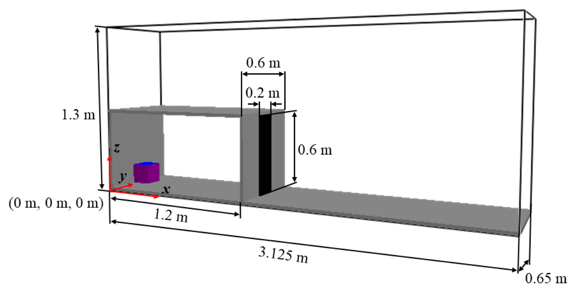
For the initial conditions inside the compartment for the numerical calculation of the mass inflow and outflow in a compartment without fire, the insufficient ventilation condition was used according to the experimental study on backdraft by Weng and Fan[15]. Figure 3 shows the calculation target for a compartment without fire. The dimensions of this compartment are 1.2m × 0.6m × 0.6 m, while the opening had dimensions of 0.2m × 0.6m with the shape of a door.
The grid system was constructed to have a uniform grid size of 2.5 cm, confirmed as appropriate through previous studies[11]. As shown in Table 1, the initial mixer inside the compartment was designed so that the chemical composition inside the compartment was uniformly distributed. The internal temperature of the compartment was designed to be 50, 100, and 200 °C. A total of 24 numerical sensors along the midline of the opening were positioned at equal intervals to check the velocity and pressure changes according to the height of the opening under all conditions.
A parallel MPI calculation through 10 cores was performed using the same computing resources used for the calculations in case of fire. The calculation lasted up to 10 CPU h per condition.

4. Results and Discussion

4.1 Conditions with a fire inside the compartment

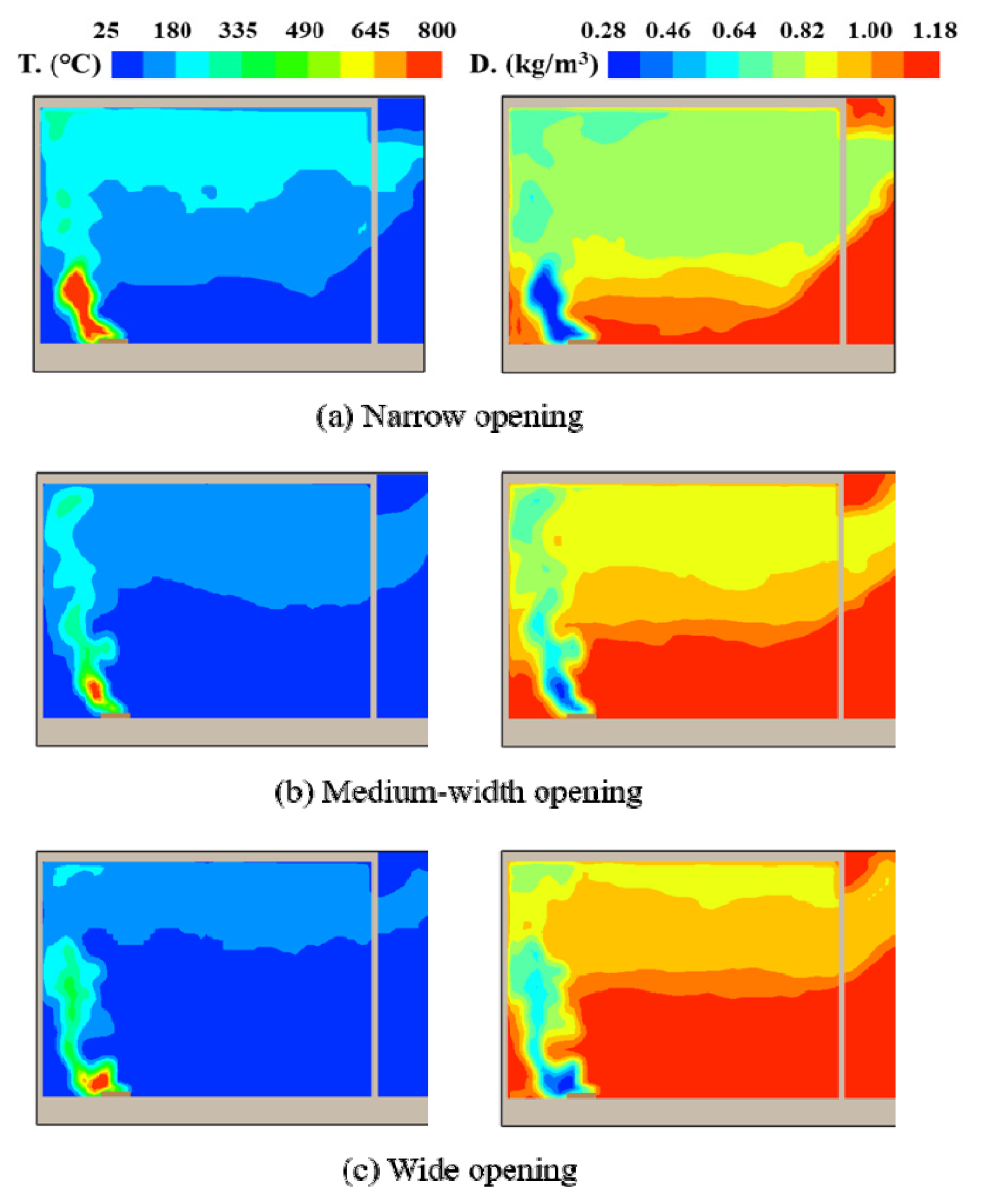
Figure 4 shows the temperature and density distribution in the middle section of the compartment (y = 1.45 m) at the moment when the calorific value reaches 62.9 kW obtained by a calculation using FDS for the condition where there is a pool fire inside the compartment. For all three opening conditions, the high-temperature smoke generated from the fire rises to the upper level of the compartment due to buoyancy and is discharged out of the compartment. The buoyancy effect is caused by the density difference due to the temperature difference between the plume and surrounding area by the fire. At a smaller width of the opening, the smoke generated by the fire was more difficult to dissipate. As a result, with the harder smoke, the hot soft layer more descends and can be seen near the bottom.
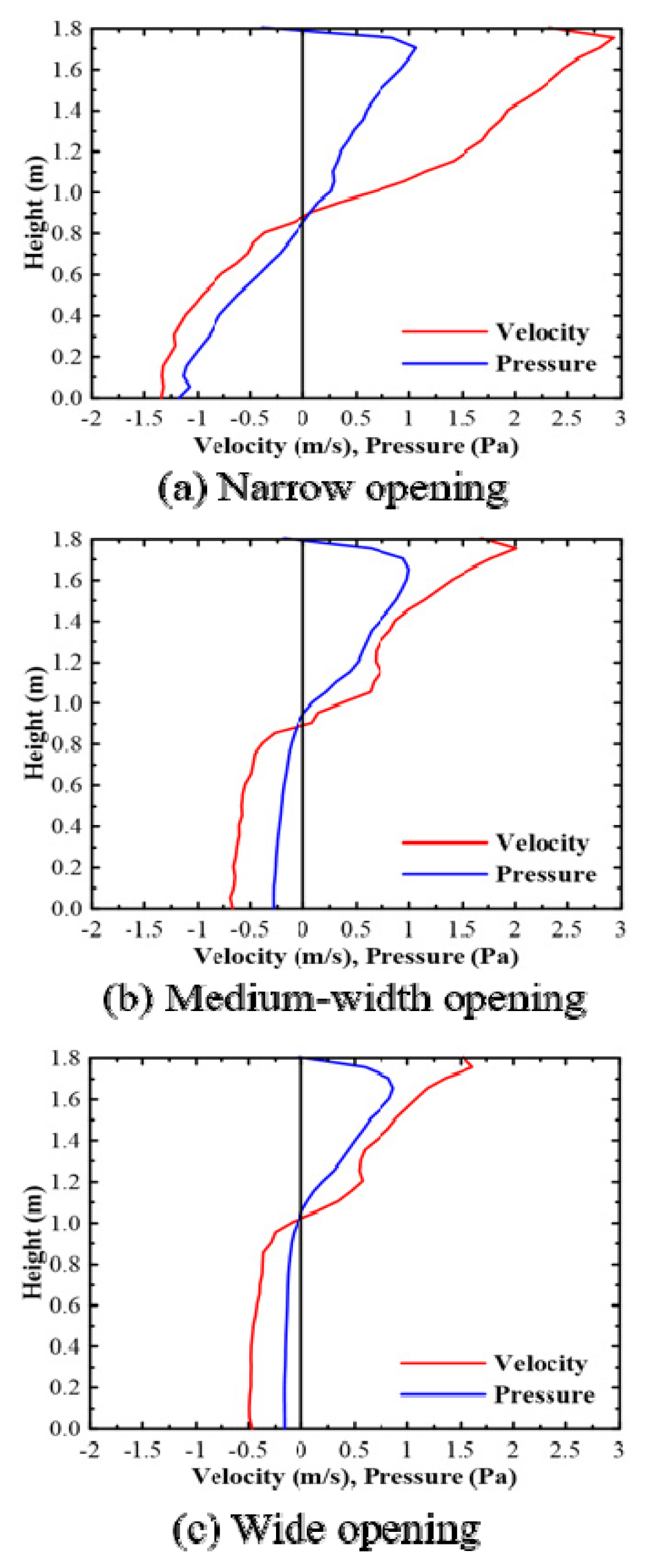
Figure 5 shows the velocity and pressure according to the height in the middle section of the opening calculated using FDS to check the flow of fluid through the opening. Under all opening conditions, the velocity and pressure have positive (+) values in the upper part and negative (−) values in the lower part. A positive value implies that the pressure is higher than the atmospheric pressure outside the compartment, which implies that there is flow from the inside to the outside of the compartment, while a negative value corresponds to the opposite flow. In addition, the flow rate has a nonzero value, which implies that there is a flow from the inside of the compartment room; the pressure and speed distributions are corrupted. In the middle of the opening, we can analyze the neutral plane having a value of 0, which is defined as the height of this neutral surface. The height of the neutral plane of each opening condition is in the order of narrow (0.966 m) < medium width (1.056 m) < wide (1.085 m). As mentioned, a narrower opening led to a lower position of the neutral plane, because the soft layer descends further to prevent smoke evacuation. The maximum and minimum values of speed and pressure increase as the opening becomes narrower, because, as explained by the previous temperature distribution, a smaller width led to a higher temperature in the upper part of the compartment room, which increased the temperature difference between the inside and outside of the compartment room and led to a higher density difference. If the density difference inside and outside the division increases, the air that enters through the opening is affected by these density differences, which leads to a higher flow rate.
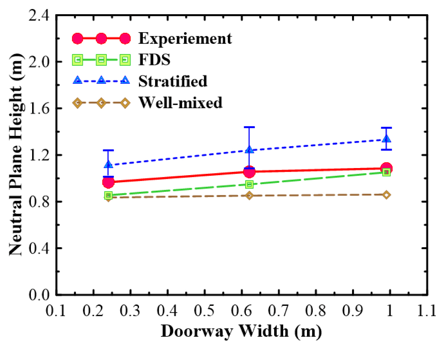
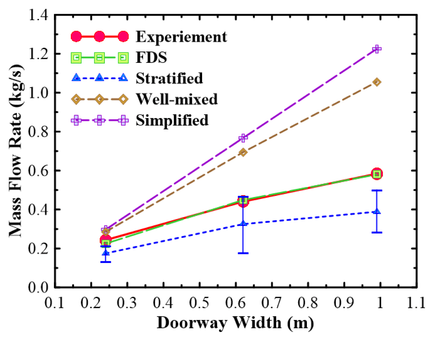
Figures 6 and 7 show the neutral plane height and inlet air mass flow according to the opening width obtained by theoretical and numerical calculations. Among the theoretical equations, the simplified model cannot be used to calculate the neutral plane, so that it is not shown in Figure 6. The neutral plane height was calculated by the stratified model considering the error range measured in the experiment; the range error bar is presented. Figure 6 shows that the results calculated by FDS are most similar to the experimental values. The neutral surface height calculated by the theoretical model is similar to the experimental results. For the calculation with the stratified type, it was slightly lower than the experimental value, while that calculated by the well-mixed method was slightly higher than the experimental value. In addition, the prediction tendency for neutral surfaces as the opening width increases was roughly similar to those of both stratified theoretical and numerical calculations.
However, the well-mixed calculation formula considers the height of the opening and density of the air and smoke, so that it does not seem to reflect the effects of the opening width. According to the inlet air mass flow rate in Figure 7, both theoretical formula and numerical calculation results predict the tendency of the mass flow rate to increase as the width of the opening increases, as obtained in the experiments. In particular, the FDS numerical result very well predicts the experimental value. Among the theoretical results, the stratified results are most similar to the experiment results. The well-mixed and simplified model results are more predictive than the experimental value as the width of the opening increases. In the wide case, the well-mixed model over-predicts by approximately 1.5 times, while the simplified model by approximately two times. This occurs as the calculations assume that the well-mixed and simplified compartments are filled with a high-temperature smoke without any distinction between the smoke layers in the actual compartment.

4.2 Conditions without fire inside the compartment

In the case of a fire inside the compartment, it was confirmed that the results calculated by FDS for the neutral plane height and inlet air mass rate reasonably predict the values obtained in the experiment. If there is no fire in the compartment, there is no experimental result that can be easily compared to theoretical or numerical calculation results. Thus, we compare the FDS result to the result obtained by the theoretical equation. Figure 8 shows the distribution of oxygen concentration according to the time under each initial temperature condition obtained using FDS. The fuel mixer is uniformly distributed in the area with a low oxygen concentration inside the compartment room. At the same time, the opening under all three temperature conditions is open, and the gravity current phenomenon by density between the outside air and internal mixer can be confirmed. This gravitational flow shows that outside air enters the compartment through the lower part of the opening at the same time as the opening is opened. Owing to this gravitational flow, the oxygen concentration is high near the bottom of the compartment. Oxygen introduced through gravity flow is mixed with the gas inside to form a combustible zone. In addition, the high-temperature mixer inside flows out through the upper part of the opening. Although there is no fire inside the compartment, the inflow of air and outflow of the hot mixer through the opening of the compartment filled with a high-temperature homogenous mixer exhibit characteristics similar to those of the inflow of air and outflow of smoke in a fire. The mixing region (mixing layer) between the introduced air and internal mixer can be considered as a region where the high-temperature mixer is located above and region where the introduced air is distributed. Thus, the temperature of the mixer inside the compartment also affects the amount of inflow and outflow gas, which is considered in detail using the following figure.
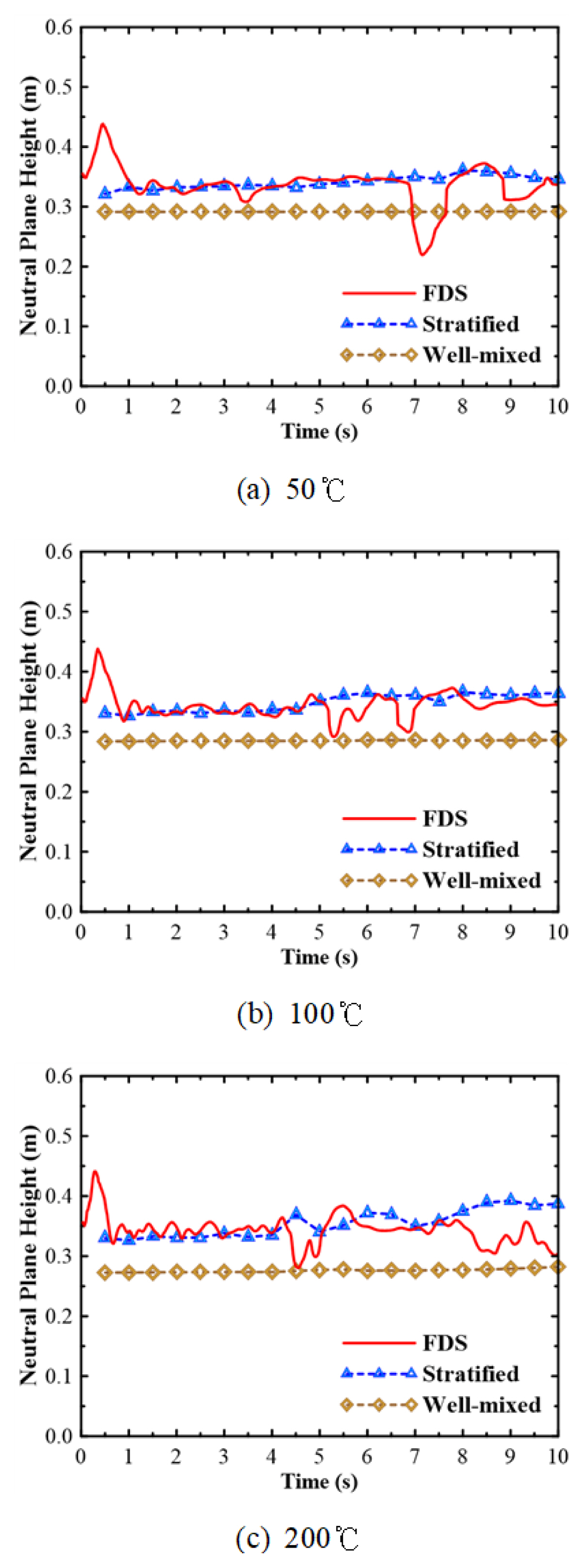
Figure 9 shows the neutral plane height calculated by the theory and FDS for the conditions at the initial temperature in the compartment. The theoretically calculated values show a similar trend to the FDS results. However, in terms of accuracy, the stratified formula result is more similar to the FDS result than the well-mixed formula result. Notably, the current calculations are carried out for the uniform internal mixer. However, for the neutral plane height, the stratified equation results agree better with the FDS results than with the well-mixed equation results.
To compare the theoretical equation result to the mass flow calculated by FDS, Figure 10 shows the mass flow calculation results over time for each initial temperature condition. As the theoretical result is calculated under the assumption that the inflow and outflow are same, there is no difference between the inflow and outflow. This tendency becomes larger as the initial temperature inside the compartment increases, which confirms that the inflow mass rate is considerably larger than the outflow mass rate. In addition, both inflow and outflow masses decrease with time, but the decreasing trend is more evident in the inflow mass. If we consider the inflow mass, the well-mixed formula results match the FDS results best at the initial stage at 50 °C where the internal temperature of the compartment is low. However, as the temperature increases, the FDS calculation results become higher than those calculated by the theoretical formula. In other words, the well-mixed equation is slightly better in the prediction of the air inflow mass rate. However, overall, the theoretical equation does not predict the mass flow rate calculated by the FDS to a satisfactory level. On the other hand, for the effluent mass, the simplified formula results agree well with the FDS results regardless of the temperature conditions.

5. Conclusion

To evaluate the prediction accuracy of the theoretical equations proposed for the inflow and outflow of internal mixer mass through the opening of the compartment, experiments on mass flow in compartments with openings and numerical calculations using FDS were performed. The conclusions of this study can be summarized as follows.
  1. The height of the neutral plane calculated using the theory and FDS under the condition of fire inside the compartment well obeyed the trend of the experiment. In particular, the FDS results for the neutral plane height and inlet air mass flow well agreed with the experiment. However, for the inlet air mass flow rate, the theoretically obtained stratified and well-mixed model equations over-estimated the mass flow change trend according to the increase in the opening width.

  2. The stratified model equation was most consistent with the FDS calculation results regardless of the temperature conditions under the condition of a uniform mixture inside the compartment. However, with respect to the air inflow, the well-mixed model formula result was most similar to the FDS result, but the overall difference was not small. On the other hand, for the effluent air flow rate, the simplified formula result was most consistent with the FDS results.

The results reviewed in this study can be helpful in judging the usefulness of the previously proposed simple formulas for calculation of the mass inflow and outflow through the opening of the compartment.

Notes

Author Contributions

Conceptualization, S.H. and C.B.O.; investigation, S.H. and C.B.O; formal analysis, S.H. and C.B.O; writing—original draft preparation, S.H.; writing—review and editing, C.B.O.; supervision, C.B.O. All authors have read and agreed to the published version of the manuscript.

Conflicts of Interest

The authors declare no conflict of interest.

Figure 1
Schematic of the compartment geometry and fuel pool location.
kifse-19d48c0ff1.jpg
Figure 2
Geometries of the three compartment openings for the fire case simulation: (a) narrow, (b) medium width, and (c) wide.
kifse-19d48c0ff2.jpg
Figure 3
Geometry of the compartment and opening for the non-fire case simulation.
kifse-19d48c0ff3.jpg
Figure 4
Temperature and density distributions at the middle plane of the compartment (y = 1.45 m) when the heat release rate of fire reaches 62.9 kW for different opening geometries: (a) narrow, (b) medium width, and (c) wide; left-hand side: temperature, right-hand side: density.
kifse-19d48c0ff4.jpg
Figure 5
Velocity and pressure distributions with the height of compartment opening: (a) narrow, (b) medium-width, and (c) wide openings.
kifse-19d48c0ff5.jpg
Figure 6
Comparison of the theoretical and numerical results of neutral plane height according to the opening width.
kifse-19d48c0ff6.jpg
Figure 7
Comparison of the theoretical and numerical results of inflow air mass rate according to the opening width.
kifse-19d48c0ff7.jpg
Figure 8
Temporal distribution of oxygen mass fraction for the door condition at each initial temperature in the compartment at a plane with y = 0.325 m: (a) 50, (b) 100, and (c) 200 °C.
kifse-19d48c0ff8.jpg
Figure 9
Neutral plane height for the door condition at each initial temperature in the compartment at a plane with y = 0.325 m: (a) 50, (b) 100, and (c) 200 °C.
kifse-19d48c0ff9.jpg
Figure 10
Mass flow rate for the door condition at each initial temperature in the compartment at a plane with y = 0.325 m: (a) 50, (b) 100, and (c) 200 °C; left-hand side: inflow, right-hand side: outflow.
kifse-19d48c0ff10.jpg
Table 1
Initial Species Mass Fractions and Temperature of the Mixture in the Compartment for the Non-Fire Case Simulation
Species mass fraction Temperature of the mixture in the compartment (°C)
YCH4 YO2 YCO2 YCO YN2 50 100 200
0.1224 0.1460 0.0210 0.0012 0.7094

References

1. JG Quintiere, “Fundamentals of Fire Phenomena”, John Wiley & Sons Ltd, Chichester, UK (2006).

2. JG Quintiere and CA Wade, “Compartment Fire Modeling et al”, “SFPE Handbook of Fire Protection Engineering”, Springer, New York, NY (2015), https://doi.org/10.1007/978-1-4939-2565-0_29.
crossref
3. CM Fleischmann, PJ Pagani and RB Williamson, “Exploratory Backdraft Experiments”, Fire Technology, Vol. 29, pp. 298-316 (1993).
crossref pdf
4. CM Fleischmann, “Backdraft Phenomena”, “PhD dissertation”, University of California, Berkeley (1993).

5. CM Fleischmann, PJ Pagani and RB Williamson, “Quantitative Backdraft Experiments”, Proceedings of the Fourth International Symposium of Fire Safety Science, June 13-17; Ottawa, Ontario, Canada. pp. 337-348 (1994).
crossref
6. JG Quintiere, BJ McCaffrey and K Den-Braven, “Experimental and Theoretical Analysis of Quasi-Steady Small-Scale Enclosure Fires”, Symposium (International) on Combustion, Vol. 17, No. 1, pp. 1125-1137 (1979), https://doi.org/10.1016/S0082-0784(79)80107-1.
crossref
7. JG Quintiere, WJ Rinkinen and WW Jones, “The Effect of Room Openings on Fire Plume Entrainment”, Combustion Science and Technology, Vol. 26, pp. 193-201 (1981), https://doi.org/10.1080/00102208108946960.
crossref
8. JG Quintiere, K Steckler and D Corley, “An Assessment of Fire Induced Flows in Compartments”, Fire Science and Technology, Vol. 4, No. 1, pp. 1-14 (1984), https://doi.org/10.3210/fst.4.1.
crossref
9. KD Steckler, JG Quintiere and WJ Rinkinen, “Flow Induced by Fire in a Compartment”, “NBSIR 82-2520”, National Bureau of Standards, Washington, DC, USA (1982).
crossref
10. KD Steckler, HR Baum and JG Quintiere, “Flow Induced Flows Through Room Openings-Flow Coefficients”, “NBSIR 83-2801”, National Bureau of Standards, Washington, DC, USA (1984).

11. LY Cooper, “A Note on Calculating Flows Through Vertical Vents in Zone Fire Models Under Conditions of Arbitrary Cross-Vent Pressure Difference”, Combustion Science and Technology, Vol. 64, pp. 43-50 (1989), https://doi.org/10.1080/00102208908924021.
crossref
12. B Karlsson and JG Quintiere, “Enclosure Fire Dynamics”, Environmental & Energy Engineering, (2000).
crossref
13. HW Emmons, “Vent Flows”, “The SFPE Handbook of Fire Protection Engineering”, 3rd Edition., National Fire Protection Association, Quincy, MA (2002).

14. WK Chow and GW Zou, “Correlation Equations on Fire-Induced Air Flow Rates Through Doorway Derived by Large Eddy Simulation”, Building and Environment, Vol. 40, No. 7, pp. 897-906 (2005), https://doi.org/10.1016/j.buildenv.2004.09.010.
crossref
15. L Wang and JG Quintiere, “An Analysis of Compartment Fire Doorway Flows”, Fire Safety Journal, Vol. 44, No. 5, pp. 718-731 (2009).
crossref
16. L Wang, J Lim and JG Quintiere, “On the Prediction of Fire-Induced Vent Flows Using FDS”, Journal of Fire Science, Vol. 30, No. 2, pp. 110-121 (2011), https://doi.org/10.1177/0734904111424562.
crossref
17. N Johansson and P Van-Hees, “A Simplified Relation Between Hot Layer Height and Opening Mass Flow”, Fire Safety Science-Proceedings of the Eleventh International Symposium, pp. 432-443 2014; https://doi.org/10.3801/iafss.fss.11-432.
crossref
18. K McGrattan, S Hostikka, R McDermott, J Floyd, C Weinschenk and C Overholt, “Fire Dynamics Simulator (FDS Version 632) User’s Guide”, “NIST Special Publication, 1019”, National Institute of Standards and Technology, Gaithersburg, Maryland, USA (2015).

19. K McGrattan, S Hostikka, R McDermott, J Floyd, C Weinschenk and C Overholt, “Fire Dynamics Simulator (FDS Version 6.3.2) Technical Reference Guide”, “NIST Special Publication, 1018-1”, National Institute of Standards and Technology, Gaithersburg, Maryland, USA (2015).


ABOUT
BROWSE ARTICLES
EDITORIAL POLICY
AUTHOR INFORMATION
Editorial Office
Room 906, The Korea Science Technology Center The first building, 22, Teheran-ro 7 Gil, Gangnam-gu, Seoul, Republic of Korea
Tel: +82-2-555-2450/+82-2-555-2452    Fax: +82-2-3453-5855    E-mail: kifse@hanmail.net                

Copyright © 2024 by Korean Institute of Fire Science and Engineering.

Developed in M2PI

Close layer
prev next