
1. Introduction
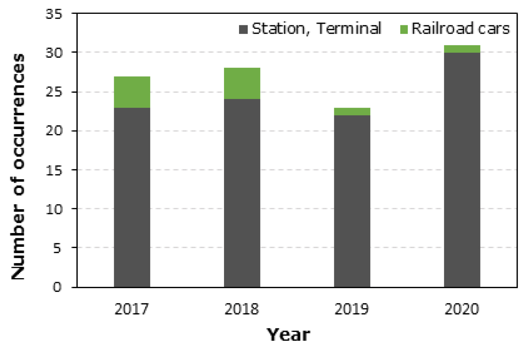
Various forms of transportation exist in modern society. In particular, subways are a means of transportation that operate in underground space and can accommodate a large number of people at once, and thereby exhibit benefits in terms of space utilization[1,2]. However, in the event of a fire in this type of underground space, such as the subway and underground shopping malls, numerous human casualties can occur. Figure 1 shows basement fire and industrial dust collector fire cases. In the event of a fire in a basement, as shown in Figure 1(a), toxic substances are spread to the outside by the emitted fire smoke. This can lead to severe secondary damage to nearby shopping malls[3]. Among various types of fine particles, dust is frequently generated from thermal power plants and industrial facilities, along with fire dust, and the dust suspended in the air in high concentrations can cause dust explosions, including combustion and explosions, when accompanied by energy such as heat and pressure[4]. Figure 1(b) shows the fire explosion case caused by dust in the dust collector’s internal filter at an industrial site. In industrial sites, fire explosions caused by dust in dust collectors and related processes occur on a regular basis[5,6]. Figure 2 shows the status of fire occurrence in stations, terminals, and railroad vehicles over the last four years[7].
Fine dust is the main cause of air pollution, and it can be classified as fine dust and ultra-fine dust according to its diameter[8,9]. This type of fine dust consists of carbon compounds, such as nitrate, sulfate, and ammonium ions, and heavy metals, and the exposure of the human body to fine dust can lead to diseases, including asthma, lung cancer, and cardiovascular diseases[10,11]. As mentioned above, research on fine dust collectors is required to reduce dust and fine dust, which can lead to various social and industrial problems.
2. Main Text
2.1 Classification and principles of dust collectors
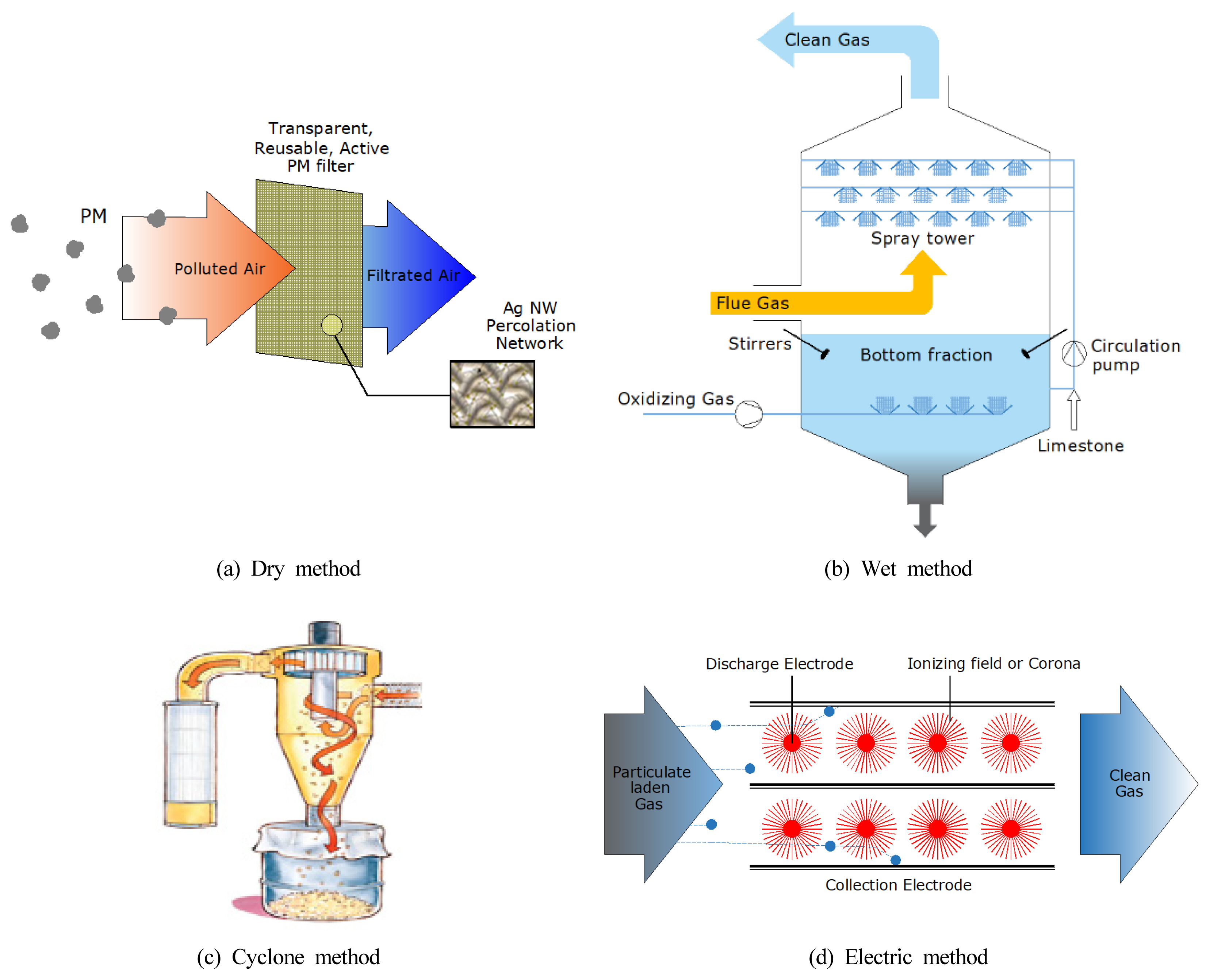
Dust collection methods to remove fine dust are mainly classified into dry, wet, cyclone, and electric methods, as shown in Figure 3[12,13,14]. Among them, the electric method has been widely used in industries and is further divided into dry and wet electrostatic precipitation methods.
Figure 4 shows the principles of dry and wet electrostatic precipitators[15]. In dry electrostatic precipitators, dust that passes between charged plates is adsorbed onto the charged plates by electrostatic characteristics, and the dust is dropped by rapping the charged plates. However, dry electrostatic precipitators have low dust collection efficiency due to the accumulation of dust in the filter and accumulated dust may cause a fire. Wet electrostatic precipitators collect dust in the same manner as dry electrostatic precipitators, and the dust adsorbed onto the charged plates is washed off by spraying water from the top. The reduction in dust collection efficiency by the accumulation of dust in the filter has been supplemented, but high injection pressure and a large amount of water are used while washing the charged plates. Furthermore, the post-treatment of water contaminated by dust is costly[16,17]. To address these problems with conventional electrostatic precipitators, studies have been actively conducted on electrospray electric precipitation. In previous studies conducted by Soyeon Kim et al., the direct charging method that directly applies high voltage to nozzles was analyzed because the method involves simple design for the application of high voltage and requires no additional equipment, such as discharge electrodes. Owing to the design limitation of the needle subjected to the direct application of high voltage and that the entire spray liquid pipeline must be grounded, research on the indirect charging method is required considering electrical safety in actual application. In this study, electrospray characteristics were compared and analyzed for the direct and indirect charging methods.
2.2 Theory of the electrospray method
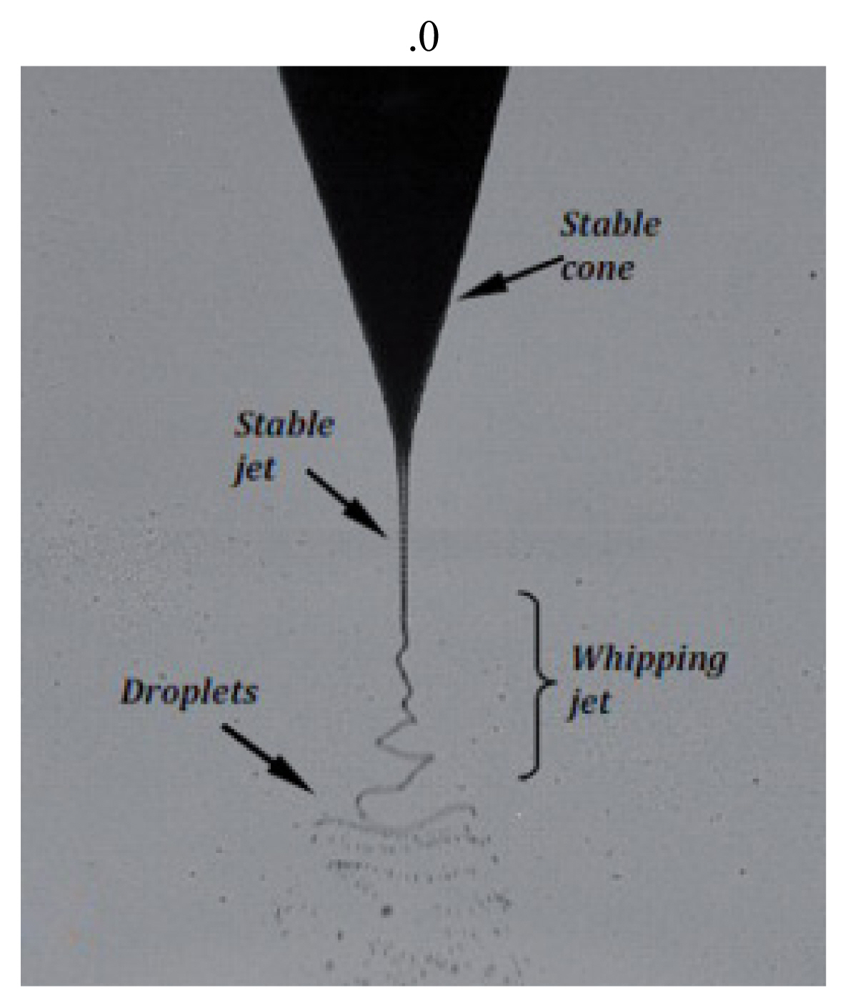
In the electrospray method, high voltage is applied to a nozzle or a discharge electrode to charge the sprayed liquid, and the charged microdroplets are sprayed to surrounding areas due to the electrostatic repulsion with each other. In this instance, negatively charged microdroplets mainly collect fine dust via electrostatic bonding with positively charged fine dust particles. The conductive liquid that passes through the nozzle exhibits various spray modes, such as the dripping mode, cone-jet mode, and multi-jet mode, based on the applied voltage[18]. Among these modes, the most stable cone-jet mode makes it possible to continuously obtain uniform microdroplet sizes unlike other spray modes[19]. Figure 5 shows the typical cone-jet mode[20].
The electrospray method can be classified into direct and indirect charging methods according to the high-voltage application method. High voltage is directly applied to the nozzle in the direct charging method, whereas high voltage is applied to the discharge electrode or discharge ring located between the nozzle and collecting electrode plate instead of the nozzle in the indirect charging method.
In the direct charging method, the spray liquid is negatively charged by applying high negative voltage to the nozzle, a conductive spraying device. The negatively charged spray liquid forms a Taylor cone and jet at the tip of the nozzle, and the negatively charged microdroplets are sprayed to surrounding areas at the end of the jet[21]. In the indirect charging method, unlike the direct charging method, high negative voltage is applied to the discharge electrode or discharge ring located between the nozzle and collecting electrode plate, and the spray liquid is negatively charged while passing through the discharge electrode or discharge ring. Then, the spray liquid is sprayed to surrounding areas in the form of microdroplets. The size of the microdroplets generated by the electrospray method can be expressed using the following Eq. (1)[22]:
where γ is the length of the microdroplets[m], Q is the flow rate of the spray liquid[m3/s], εγ is the dielectric constant of the spray liquid[C2/N·m2], ε0 is the dielectric constant in vacuum[C2/N·m2], and K is the electrical conductivity of the spray liquid[S/m].
In this study, an electrospray visualization device that can apply both the direct and indirect charging methods was fabricated, and then comparative experiments on both methods were performed to improve the dust collection efficiency of electrospray electric precipitation. Additionally, microdroplet spray characteristics were analyzed for the direct and indirect charging methods.
2.3 Configuration and contents of the experimental setup
Figures 6 and 7 show the schematics of the electrospray experimental setups for direct and indirect charging methods, respectively. The flow rate was adjusted using a syringe pump for constant spray liquid supply, and the distance adjustment jig was used to adjust the distance between the nozzle and dust collecting electrode plate or the distance between the discharge electrode plate and dust collecting electrode plate. Negative voltage was applied to the nozzle in the direct charging method, whereas negative voltage was applied to the discharge electrode plate in the indirect charging method. For both methods, the dust collecting electrode plate was grounded such that it was relatively positive. Tables 1 and 2 list the detailed specifications of the experimental setup for each charging method.
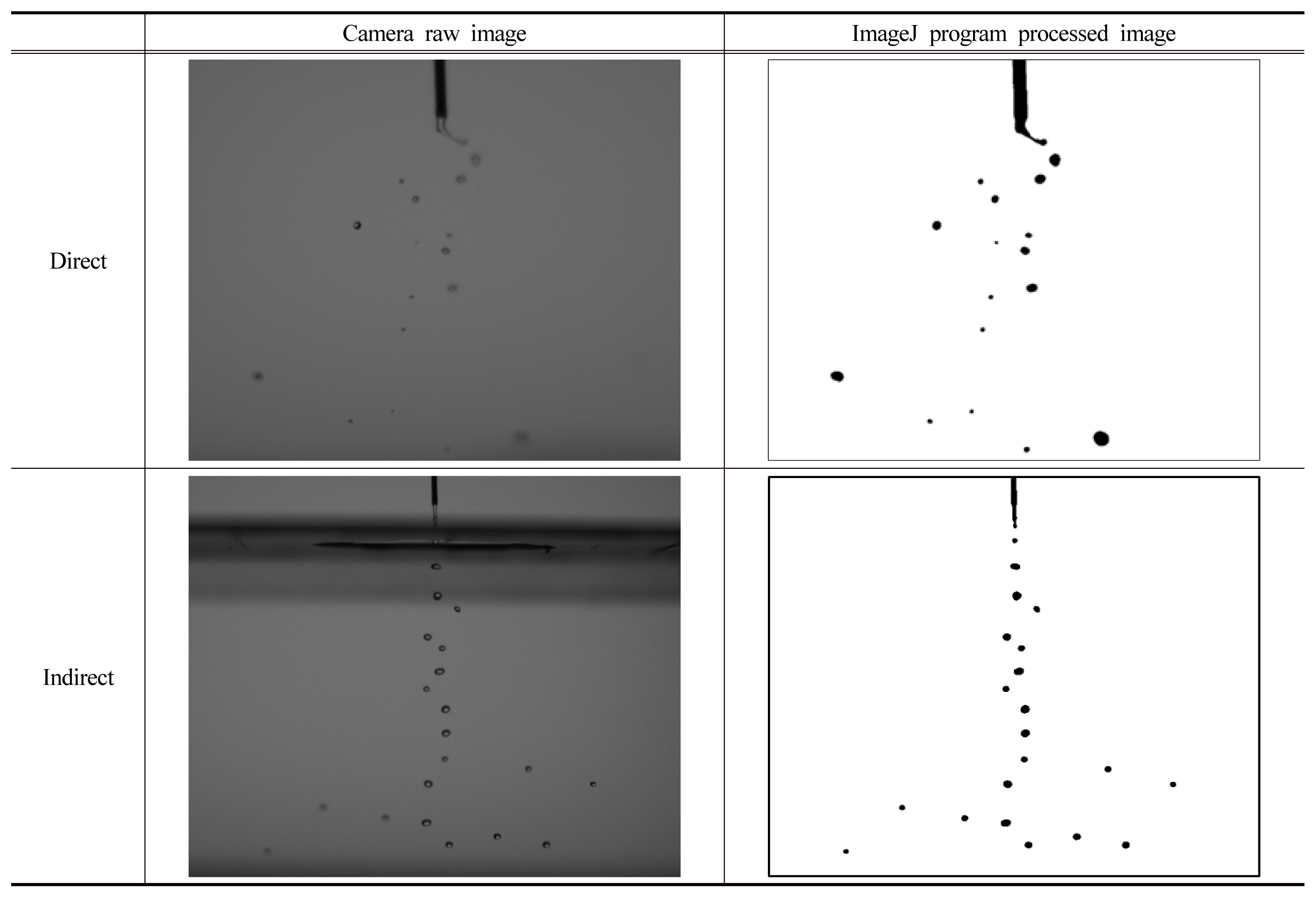
The experimental items of this study are as follows. In the visualization experiment of the direct charging method, the inner diameter of the nozzle was set to 0.85 mm and tap water was supplied at a flow rate of 10 mL/min via the syringe pump. The distance between the nozzle and dust collecting electrode plate was fixed at 7 cm, and an experiment on the microdroplet spray pattern was performed by directly applying voltages of 0, 10, 20, and 30 (−kV) to the nozzle. Meanwhile, for the indirect charging method, the inner diameter of the nozzle was set to 0.85 mm and tap water was supplied at a flow rate of 10 mL/min via the syringe pump. Gap 1, which is the distance between the nozzle and discharge electrode plate, was fixed at 0.5 cm, while Gap 2, which is the distance between the discharge electrode plate and dust collecting electrode plate, was fixed at 7 cm. The discharge electrode plate made of stainless steel had a hole with a diameter of 5 cm. Voltages of 0, 10, 20, and 30 (−kV) were applied to the discharge electrode plate. Table 3 shows the specific experimental conditions for the direct and indirect charging methods. To measure the spray shape for the direct and indirect charging methods, a high-magnification camera was placed at a certain distance from the visualization device, and experimental results were obtained via repeated experiments. The microdroplet spray shape for each charging method was photographed, and the size and number of microdroplets were finally analyzed using ImageJ software. Figure 8 shows the process of analyzing the size and number of microdroplets using ImageJ software based on the photographs taken for the microdroplet spray shape of each charging method.
3. Experimental Results
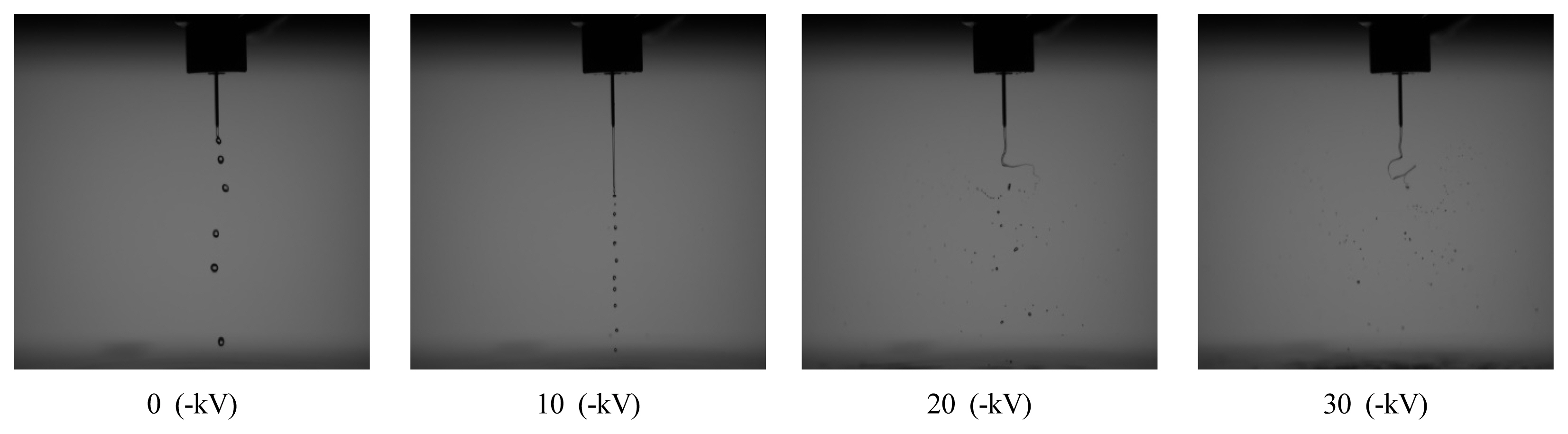
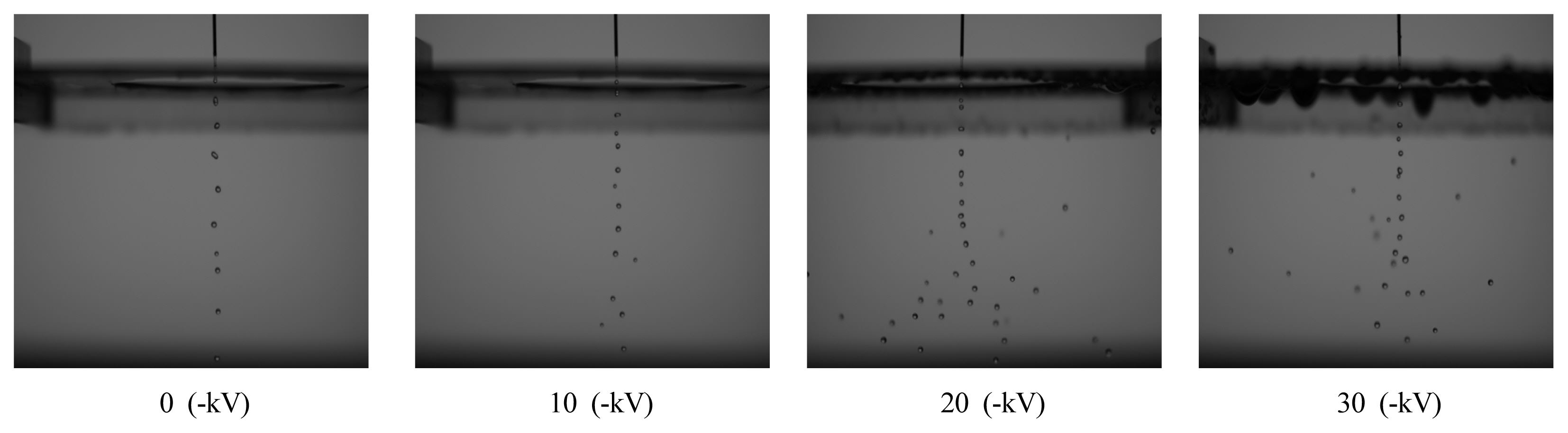
In this study, experiments on the direct and indirect charging methods were performed by setting experimental conditions as mentioned earlier to analyze the size and number of microdroplets that significantly affect fine dust collection efficiency. For each charging method, the applied voltage was varied from 0 to 10, 20, and 30 (−kV), and the size and number of generated microdroplets were analyzed using a high-magnification camera and ImageJ software. Figures 9 and 10 show the microdroplet spray shapes of the direct and indirect charging methods according to the applied voltage. For both methods, the size of microdroplets decreased and the number of microdroplets increased as the voltage increased.
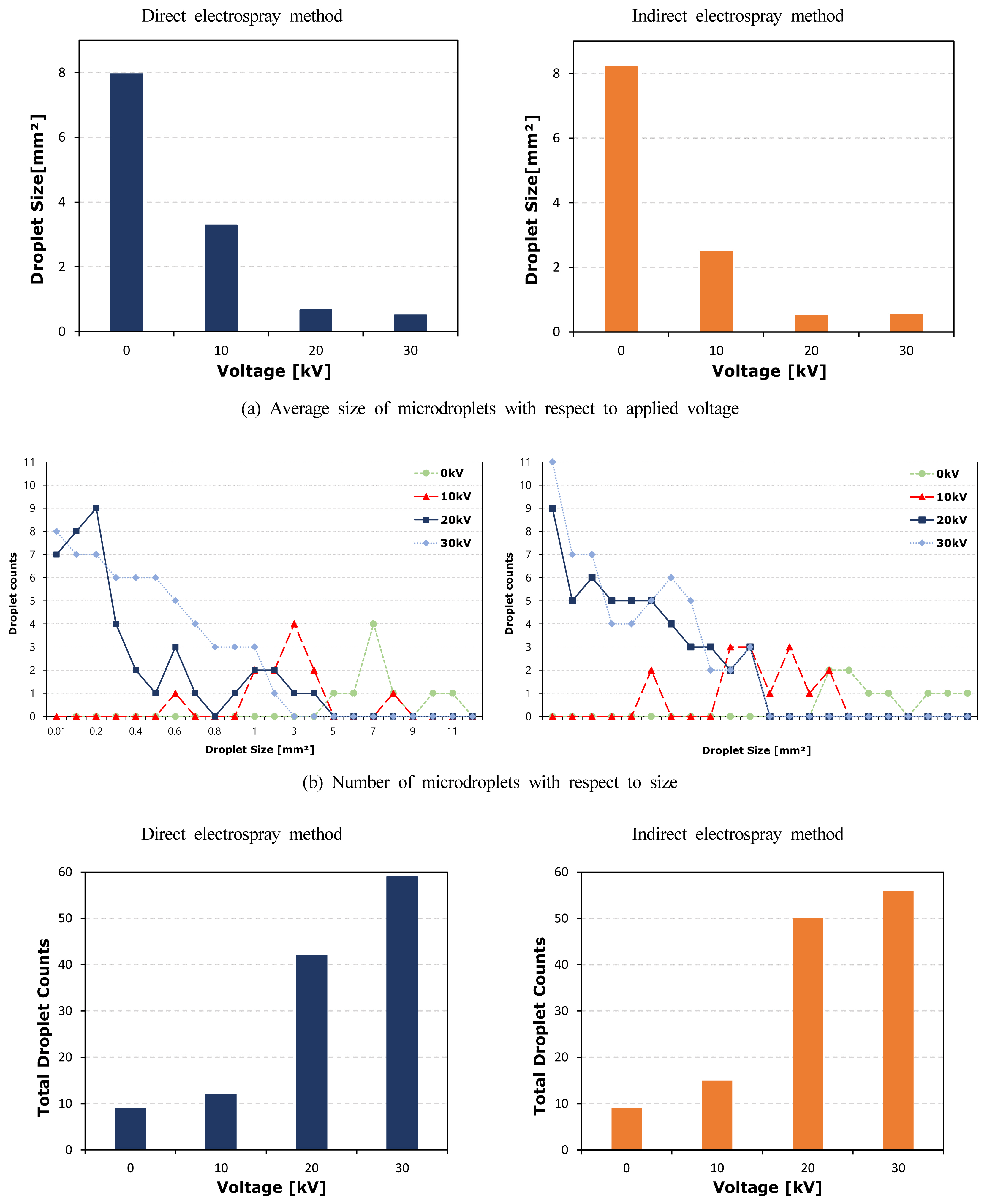
Figure 11 shows the size and number of microdroplets obtained using ImageJ software for direct and indirect charging methods when the applied voltage was varied from 0 to 10, 20, and 30 (−kV). Furthermore, the flow rate was fixed at 10 mL/min, nozzle diameter was 0.85 mm, and distance between the nozzle and dust collecting electrode plate was 7 cm. Figure 11(a) shows the average size of microdroplets, while Figure 11(b) shows the number of microdroplets by size. Figure 11(c) shows the total number of microdroplets.
As shown in Figure 11(a), the average sizes of microdroplets were 7.96, 3.29, and 0.67 mm2 for the direct charging method and 8.20, 2.48, and 0.51 mm2 for the indirect charging method at applied voltages of 0, 10, and 20 (−kV), respectively. Except for 0 (−kV), the average size of microdroplets was relatively smaller for the indirect charging method when compared to that for the direct charging method. Therefore, the indirect charging method generated relatively more microdroplets in small sizes. However, at 30 (−kV), the average size of the direct charging method (0.51 mm2) was smaller than that of the indirect charging method (0.53 mm2). This was due to the fact that voltages of 10 and 20 (−kV) were insufficient to form microdroplets by applying voltage to the continuously discharged fluid in the direct charging method as high voltage was directly applied to the nozzle. However, 30 (−kV) was sufficient to form microdroplets as sufficiently high voltage was applied to the continuously discharged fluid. A very high voltage of 30 (−kV) must be applied to generate microdroplets smaller than 0.5 mm2, and the number of microdroplets in the size range, in which it is difficult to collect fine dust, increases at an applied voltage of 30 (−kV). This is expected to decrease fine dust collection efficiency.
Figure 11(b) shows the number of microdroplets by size. It can be observed that the indirect charging method exhibits relatively more microdroplets that are larger than 0.1 mm2, which is considered the minimum size for fine dust collection, than the direct charging method when the applied voltage ranged from 10 to 20 (−kV).
Figure 11(c) shows the total number of microdroplets. The total numbers of generated microdroplets were 9, 12, 42, and 59 for the direct charging method and 9, 15, 50, and 56 for the indirect charging method when the applied voltage ranged from 0 to 30 (−kV). In the voltage range of 10-20 (−kV), which is the relatively low applied voltage range, the indirect charging method generated relatively more microdroplets than the direct charging method. At 30 (−kV), the direct charging method generated more microdroplets than the indirect charging method, but the generated microdroplets were smaller than 0.1 mm2, which is considered to be the minimum size for fine dust collection. Hence, it is difficult to expect that the direct charging method will collect fine dust more effectively than the indirect charging method at 30 (−kV).
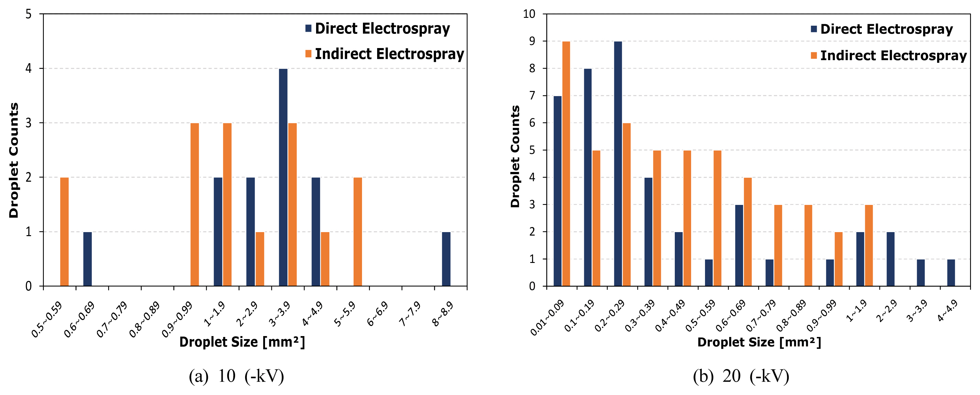
Figure 12 shows the number of microdroplets by size in the applied voltage range of 10-20(−kV), excluding 0 (−kV) and a relatively high applied voltage of 30 (−kV), for direct and indirect charging methods. The results at an applied voltage of 10 (−kV) are shown in Figure 12(a) and those at 20 (−kV) are shown in Figure 12(b). The analysis of the experiment results showed that there was no significant difference in the number of microdroplets between direct and indirect charging methods at 10 (−kV) as the number of microdroplets corresponded to 12 and 15, respectively. However, in terms of the size of microdroplets, the indirect charging method generated more microdroplets in the relatively low range of 0.5-2.9 mm2, whereas the direct charging method generated more microdroplets in the relatively large range of 3-8.9 mm2. Therefore, it can be concluded that the direct charging method can generate a small number of microdroplets and form large microdroplets at 10 (−kV) because it is not effective in generating microdroplets.
In the results shown in Figure 12(b) at an applied voltage of 20 (−kV), the indirect charging method generates relatively more microdroplets than the direct charging method as the number of generated microdroplets corresponds to 50 and 42, respectively. In terms of the size of microdroplets, the direct charging method generated more microdroplets in the range of 0.01-0.29 mm2, whereas the indirect charging method generated more microdroplets in the range of 0.3-1.9 mm2. Hence, at 20 (−kV), it can be concluded that the direct charging method forms relatively small microdroplets when compared to the indirect charging method because the applied voltage strongly acts on the spray liquid. Given that the fine dust collection capability decreases as the size of microdroplets is smaller than 0.1 mm2, the fine dust collection efficiency of the direct charging method, which is dominated by the generation of very small microdroplets, is expected to be lower than that of the indirect charging method at an applied voltage of 20 (−kV).
4. Conclusion and Future Plans
In this study, a visualization device was used and the size and number of microdroplets for the direct and indirect charging methods were analyzed via ImageJ software in the applied voltage range of 0-30 (−kV). The analysis of the experiment results showed that the size of microdroplets was inversely proportional to the voltage, and the number of microdroplets tended to increase for both charging methods. For the indirect charging method, the size of the microdroplets generated in the 0-20(−kV) range was relatively smaller and more microdroplets were generated compared to the direct charging method. In the case of the direct charging method, the size of microdroplets was relatively larger (3 to 8.9 mm2) and fewer microdroplets were generated at an applied voltage of 10 (−kV). At 20 (−kV), very small microdroplets in the range of 0.01-0.29 mm2 were dominantly formed, indicating that the direct charging method is not effective in collecting fine dust. Hence, it is considered difficult for the direct charging method to adjust the size and number of microdroplets through the applied voltage because the voltage acts on the spray liquid relatively weakly at 10 (−kV) and relatively strongly at 20 (−kV). In the indirect charging method, microdroplets in the size ranges of 0.5-5.9 mm2 and 0.2-1.9 mm2 were dominant at 10 and 20 (−kV), respectively. Hence, smaller microdroplets were formed compared to the direct charging method at a relatively low voltage of 10 (−kV), and larger microdroplets were formed compared to the direct charging method at a relatively high voltage of 20 (−kV).
The results of this study indicate that the indirect charging method is more advantageous in terms of the number and size of microdroplets compared to the direct charging method and has a wider applied voltage operation range for electrospray electric precipitation. Furthermore, the direct charging method has design limitations, such as grounding of the pipeline between nozzles, due to the direct application of high voltage to the nozzle as well as structural problems such as additional cost for safety. Therefore, the indirect charging method, which can effectively adjust the size and number of microdroplets, is considered to be advantageous for electrospray electric precipitation. In future studies, more in-depth research will be conducted on the optimal applied voltage, fine dust collection efficiency, and microdroplet generation characteristics according to the nozzle diameter, flow rate, and hole diameter of the discharge electrode plate for the indirect charging method.